
Related Manuals for ATTAIN FITNESS RB2G


Summary of Contents for ATTAIN FITNESS RB2G
- Page 1 RB2G RECUMBENT BIKE OWNER’S MANUAL Model No. RB2G Fitness Authority Industrial Co., LTD. MA902 No. 15, Xiangxue Rd., Dali Dist., Taichung City 41275, Taiwan. ATTAIN FITNESS VERSION-2023.12...
- Page 2 IT IS IMPERATIVE THAT YOU FILL IN THE FOLLOWING INFORMATION AND REFER TO IT SHOULD THE NEED FOR SERVICE ARISE. Product Name: RB2G RECUMBENT BIKE Serial # _ _ _ _ _ _ _ _ _ _ _ Serial No.:...
- Page 3 TABLE OF CONTENTS Product Safety…….…….……….…………….….….….….….……….….….…….………1 Parts Contents……….….….….….……….….….….….….……….…….….….…….……2 Assembly….……….….….……….….….….….……….……………….….….……………3 Adjustments………….………………….….……….….….……….….….….….….………6 Detailed Parts List.……………………….……….….….….….…………….……………..8 Exploded Drawing.…………….……….……….……….……….….…………….………..11 Computer Operation………………………….…………….…………….…………………13...
- Page 4 5. Do not attempt any maintenance or adjustments other than those described in this manual. Should any problems arise, discontinue use and consult an Authorized Service Representative. Please call your local dealer for assistance or ATTAIN FITNESS at +1 877-551-7484 and info@attainfitnessusa.com 6.
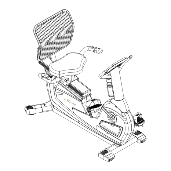
- Page 5 RB2G PARTS CONTENTS Rear Stabilizer Front Stabilizer Main Bike Assembly Right Left Seat Pad andlebar Handlebar Console Mast Back Pad Bottle Water Console Computer Cover Holder Bottle Mast Console Cover Mesh Back Pad Left Right Pedal Pedal...
- Page 6 ASSEMBLY Step 1 Front & Rear Stabilizer 1. Use a Styrofoam block from the packing material to raise the front of the Bike Assembly then a�ach the Front Stabilizer (2) using two 3/8" x 2-1/4" Hex Head Bolts (79), as shown in Fig.
- Page 7 ASSEMBLY Step 3 Handlebars Pulse Handlebar Wire (42) to the Pulse Coiled Wire (41) on the Seat Frame (5). Store excess Spring Washers (104), and two M8 x 15L Dome Head Allen Bolts (84) as shown in Fig. C1. Insert the Seat Adjustment Handle (11) into the bracket welded to the Seat Frame (5). As M8 x 8L Set Screws (97) and then tighten the Set Screws (97) against the flat side.
- Page 8 ASSEMBLY Step 5 Console Mast & Computer Console Be Careful not to pinch any of the wires while assembling IMPORTANT the Console Mast and Computer. NOTE! Slide the Console Mast Cover (30) onto the Console Mast (6). See Fig. E1 and E2. Hold the Console Mast (6) close to the Bike Assembly and connect both wires;...
- Page 9 BATTERY INSTALLATION ATTENTION! Battery must be connected before using this console. Please open the battery cover and connect the battery plug to activate the console. Failure to do so will result console to malfunction. Must connect this plug in order for the console to operate.
- Page 10 ADJUSTMENTS The seat can adjust front-to-back to accommodate your leg length. Simply rotate the Seat Adjustment Handle (11) upward to loosen then rotate downward with force to lock the seat into place. The Mesh Back Support (18) can be adjusted for your comfort.
- Page 11 DETAILED PARTS LIST DESCRIPTION QTY. MAIN FRAME FRONT STABILIZER REAR STABILIZER SLIDING SEAT TRACK SEAT FRAME CONSOLE MAST LEFT HANDLEBAR RIGHT HANDLEBAR BACK SUPPORT FRAME SEAT TRACK BACKING PLATE BACK PAD ADJUSTMENT LEVER SEAT ADJUSTMENT HANDLE 12 L LEFT CRANK ARM 12 R RIGHT CRANK ARM ASSIST SHOCK...
- Page 12 DETAILED PARTS LIST DESCRIPTION QTY. 33 L LEFT SHROUD (pre-assembled) 33 R RIGHT SHROUD (pre-assembled) BRAKE MOTOR ASSEMBLY 34-1 8 PIN CONSOLE MAST HARNESS 8 PIN CONSOLE MAST HARNESS POWER RECEPTACAL HARNESS 36-1 HARNESS OF CONTROL BOARD AND SELF-POWERED GENERATOR SYSTEM SPEED SENSOR PICKUP CABLE 6 PIN 4 PIN CONSOLE MAST HARNESS PULSE CONNECTHARNESS...
- Page 13 DETAILED PARTS LIST DESCRIPTION QTY. 1/2" X 3-1/2" HEX HEAD BOLT 3/8" X 2-3/4" HEX HEAD BOLT 3/8" X 2-1/4" HEX HEAD BOLT M8 X 85L HEX HEAD BOLT M8 X 20L HEX HEAD THREADED BOLT M8 X 40L DOME HEAD ALLEN BOLT M8 X 20L DOME HEAD ALLEN BOLT M8 X 15L DOME HEAD ALLEN BOLT M8 X 30L FLAT HEAD ALLEN BOLT...
- Page 14 EXPLODED VIEW 1 of 2 104 119...
- Page 15 34-1 EXPLODED VIEW 2 of 2 36-1...
- Page 16 SG52027 SERIES INSTRUCTION MANUAL DISPLAY FUNCTIONS ITEM DESCRIPTION TIME Count up - No preset target, Time will count up from 00:00 to maximum 99:59 with each increment is 1 minute. Count down - If training with preset Time, Time will count down from preset to 00:00. Each preset increment or decrement is 1 minute between 00:00 to 99:00.
- Page 17 KEY FUNCTION ITEM DESCRIPTION Increase resistance level Setting selection. Decrease resistance level Setting selection. Confirm setting or selection. Press and hold for 2 seconds, computer will reboot and start from user setting. Reverse to main menu during preset workout value or stop mode. Start or Stop workout.
- Page 18 OPERATION PROCEDURE POWER ON Fully assembled your exercise machine and correctly positioned. Start Pedaling above 15RPM, computer will power on with a long beep sound and display all segments on LCD for 2 seconds (Drawing 1). Stop pedaling, computer will remain on for 90 seconds (when battery is fully charged) then will automatically turn off. Drawing 1 Then enter into User data setting.
- Page 19 Built in Wireless Heart Rate Receiver Note: Chest strap transmitter does not come with this unit; contact ATTAIN FITNESS, or your dealer for purchase. This product is equipped with a built-in receiver for your heart rate monitoring. Any heart rate telemetry strap that transmits at 5Khz is compatible.
- Page 20 1. Use UP or DOWN key to select workout program, choose H.R.C) and press MODE key to get into. 2. Use UP or DOWN key to select 55% (Drawing 11),75%(Drawing 12),90% (Drawing 13) or TAG (TARGET H.R., default: 100) (Drawing 14). When select TAG, use UP or DOWN key to set value 30~230, and press MODE key to confirm.
- Page 21 Drawing 16 RECOVERY (In heart rate status, press RECOVERY key to get into.) After exercising for a period, keep holding on hand grips or wearing chest strap and press RECOVERY key. All function display will stop except “TIME” starts counting down from 00:30 to 00:00 (Drawing 17). Screen will display your heart rate recovery status with the F1, F2 .to F6 (Drawing 18).
- Page 22 Drawing 23 Drawing 24 Drawing 25 Advice symbol THIN PLUMP Noted: 1. After 90 seconds without pedaling or pulse input, console will automatically turn off. Press any key can not wake the console up. Start Pedaling above 15RPM, computer will power on again. 2.
- Page 23 *This warranty is in lieu of all warranties, expressed or implied, and/or all other obligations or liabilities on our part and we neither assume nor authorize any person to assume for us any other obligation or liability in connection with the sale of your ATTAIN FITNESS product.
Need help?
Do you have a question about the RB2G and is the answer not in the manual?
Questions and answers