Advertisement
Quick Links
Serial Number Location
1 0
1 1
1 2
1 3
1 4
1 5
1 6
1 7
1 8
1 9
2 0
2 1
2 2
2 3
2 4
2 5
2 6
ATTAIN
S E R I A L
1 2 3 4 5 6 7 8
Record your Serial number
and purchase date here:
S/N __________________
DATE:________________
DEALER:______________
______________________
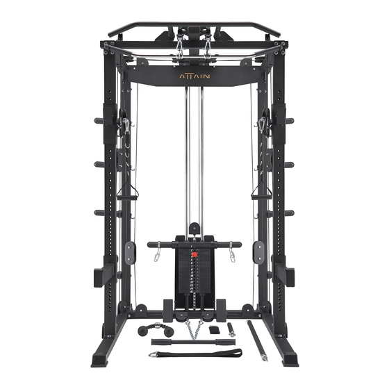
Model No. SUPER GYM 1
MK20761
ATTAIN FITNESS
SUPER GYM 1
OWNER'S MANUAL
6
7
8
9
1 0
1 1
1 2
1 3
1 4
1 5
1 6
1 7
1 8
1 9
2 0
2 1
2 2
2 3
2 4
2 5
2 6
Fitness Authority Industrial Co., LTD.
No. 15, Xiangxue Rd., Dali Dist.,
Taichung City 41275, Taiwan.
6
7
8
9
1 0
1 1
1 2
1 3
1 4
1 5
1 6
1 7
1 8
1 9
2 0
2 1
2 2
2 3
2 4
2 5
2 6
Advertisement

Related Manuals for ATTAIN FITNESS SUPER GYM 1


Summary of Contents for ATTAIN FITNESS SUPER GYM 1
- Page 1 1 2 3 4 5 6 7 8 Record your Serial number and purchase date here: S/N __________________ DATE:________________ DEALER:______________ ______________________ Model No. SUPER GYM 1 Fitness Authority Industrial Co., LTD. No. 15, Xiangxue Rd., Dali Dist., MK20761 Taichung City 41275, Taiwan. ATTAIN FITNESS...
- Page 2 7. Make certain all cables are seated within the pulleys before every use. 8. Exercise with care to avoid injury. 9. If you are unsure about the proper use of the ATTAIN FITNESS SG1, call your local ATTAIN FITNESS dealer or our customer service department.
- Page 3 Gym Placement Planner 72” 65.2” HEIGHT 83.3" Important Notes and Tips: Recommended Tools 1. Do not tighten bolts until instructed. for Assembly 2. Two people are required for the safe assembly of this product. 3. Use window cleaner or water to assist with sliding roller pads on to tubes.
- Page 4 SG1 PARTS LIST 1 NOTE: If you are missing a listed part, it likely has been pre-installed in our factory for quality control purposes. Please con�nue with assembly. *Parts images are not to scale. (1) BASE FRAME (2L) LEFT (3R) RIGHT BASE FRAME BASE FRAME (7L) LEFT...
- Page 5 SG1 PARTS LIST 2 NOTE: If you are missing a listed part, it likely has been pre-installed in our factory for quality control purposes. Please con�nue with assembly. *Parts images are not to scale. (22) DOUBLE CABLE (23) LAT BAR (24) BRACKET (25) WEIGHT (28) LEVER...
- Page 6 SG1 PARTS LIST 3 NOTE: If you are missing a listed part, it likely has been pre-installed in our factory for quality control purposes. Please con�nue with assembly. *Parts images are not to scale. (71) PULLEY COLUMN CABLE (74) HEAD OF CABLE X 3pcs (72) TOP CABLE X 2pcs (73) LOW CABLE X 2pcs...
- Page 7 STEP 1 Assemble Base Frame 1. Cap four 75W X 45H End Caps (36) to Left & Right Base Frame (2L & 3R). 2. Cap two 25 X 75mm Plugs (38) to Base Frame (1). 3. Please attach Left & Right Base Frame (2L & 3R) to the Base Frame (1) using four 1/2”...
- Page 8 STEP 2 Assemble Upright Frame 1. Cap two 45 X 75mm Plugs (37) to Rear Upright Frame (5). Please attach two Rear Upright Frames (5) to the Left & Right Base Frames (2L & 3R).using four 1/2” X 1“ Hex Threaded Bolts (80) and four 1/2” Washers (94). 2.
- Page 9 STEP 3 Assemble Top Frame 1. Attach Lat Bar Bracket (23) to Front Upright Frame (4) and Left Top Frame (15L) using two 1/2” X 3” Hex Bolts (78), four 1/2” Washers (94) and two 1/2“ Nylon Nuts (97). Attach Rear Upright Frame (5) to the Left Top Frame (15L) using two 1/2”...
- Page 10 STEP 4 Assemble Rear Top Frame & Chin Up Frame 1. Cap two 45mm SQ. Plugs (39) to Chin Up Frame (12). Attach Chin Up Frame (12) to the Left & Right Top Frame (15L & 16R) using four 1/2” X 3” Hex Bolts (78) and four 1/2”...
- Page 11 STEP 5 Assemble Connector Top Frame 1. Attach two Top Frame Pulley Brackets (18) to the Connector Top Frame (13) using two 1/2” X 6” Hex Bolts (75), four 1/2” Washers (94) and two 1/2” Nylon Nuts (97). 2. Attach Connector Top Frame (13) to Chin Up Frame (12) and Rear Top Frame (11) using two 1/2”...
- Page 12 STEP 6 Assemble Guide Rods & Weight Plate If you have 19 Weight Plates, DO NOT install the IMPORTANT two Stack Spacers (34), See figure 2 & 3 below. Before beginning Step 6, please read the following and refer to Figures 2 and 3 on the next page. - If you have 14 Weight Plates (35) per stack, install the Stack 150 lb Spacers (34) onto each of the Guide Rods (6).
- Page 13 STEP 6 Assemble Guide Rods & Weight Plate Fig 1. Fig 2. 14 Weight Plates Slight Angle 150 lbs stack Fig 3. 19 Weight Plates 200 lbs stack...
- Page 14 STEP 7 Assemble Pulley Column Cable Pulley Column Cable (71) Bolt End Ball End Head of Cable (74) Simultaneously assemble cables and pulleys. 1. Refer to T1 & T2. Mount two Pulleys (62) using two 3/8” X 1-3/4” Hex Bolts (82) and two 3/8”...
- Page 15 STEP 7 Assemble Pulley Column Cable Bolt End Pulley Column Cable (71) Ball End Head of Cable (74) T1,T2 T6,T7 T8,T10 T11,T12,T14 T16,T17...
- Page 16 STEP 8 Assemble Top Cable Top Cable (72) Bolt End Ball End Simultaneously assemble cables and pulleys. 1. Refer to A1. Mount a Pulley (62) using 3/8” X 1-3/4” Hex Bolt (82) and 3/8” Thicker Nylon Nut (99) to the pulley bracket of Connector Top Frame (13). Insert the Bolt End of Top Cable (72) into Connector Top Frame (13) and pull it out towards.
- Page 17 STEP 8 Assemble Top Cable Top Cable (72) Ball End Bolt End A1,B1 A2,B2 A5,B5...
- Page 18 STEP 9 Assemble Low Cable Threaded Bolt End Bolt End Low Cable (73) Head of Cable (74) Simultaneously assemble cables and pulleys. 1. Refer to L1. Thread the threaded bolt end of Low Cable (73) into Right Pulley Height Adjuster (10R). 2.
- Page 19 STEP 9 Assemble Low Cable Threaded Bolt End Low Cable (73) Bolt End Head of Cable (74)
- Page 20 STEP 10 Assemble Top Panel & Stack Guard 1. Attach Top Panel (14) to the Rear Top Frame (11) using four M6 X 40L Hex Socken Dome Bolts (88) and four Plastic Studs (51). 2. Attach Stack Guards (17) to the Base Frame (1) using four 5/16“ X 1/2”...
- Page 21 STEP 11 Assemble Olympic Adapter Sleeve 1. Attach eight Lever Support Rods (28), eight Rubber Cushions (45) and eight Olympic Adapter Sleeves (63) to each side of Rear Upright Frame (5) using six Weight Holder Brackets (25), eight 3/8” Washers (95) and eight 3/8“ X 1” Hex Threaded Bolts (83).
- Page 22 STEP 12 Accessories Placement 1. Remove all slack in the cables by adjusting the Cable Bolts on the Left & Right Pulley Height Adjusters (9L & 10R), and the Pulley Block (21) located on the Top Plates of the stack. Tighten all Jam-Nuts when finished. The Cable Bolts and Pulley Block (21) should not be able to rotate when tightened.
- Page 23 EXPLODED 62 51 89 52 62 48 97 94 62 37 92 63 92 63 92 63 57 55 82 22 62...
- Page 24 COMPLETE PARTS CHART NO. DESCRIPTION QTY. BASE FRAME LEFT BASE FRAME RIGHT BASE FRAME FRONT UPRIGHT FRAME REAR UPRIGHT FRAME GUIDE ROD LEFT SAFETY ARM RIGHT SAFETY ARM LEFT PULLEY HEIGHT ADJUSTER RIGHT PULLEY HEIGHT ADJUSTER REAR TOP FRAME CHIN UP FRAME CONNECTOR TOP FRAME TOP PANEL LEFT TOP FRAME...
- Page 25 COMPLETE PARTS CHART NO. DESCRIPTION QTY. SELECTOR ROD LAT BAR CURL BAR TWO WAY TOP PLATE TOP GUIDE ROD HOLDER STACK SPACER 10 LB. WEIGHT PLATE 75W X 45H END CAP 45 X 75mm PLUG 25 X 75mm PLUG 45mm SQ. PLUG HOLLOW PLUG 1”...
- Page 26 COMPLETE PARTS CHART NO. DESCRIPTION QTY. PULLEY COLUMN CABLE TOP CABLE LOW CABLE HEAD OF CABLE 1/2” X 6” HEX BOLT 1/2” X 4-1/4” HEX BOLT PLASTIC COVER 1/2” X 3” HEX BOLT 1/2” X 2-3/4” HEX BOLT 1/2” X 1” HEX THREADED BOLT 3/8”...
- Page 27 Guide Rods (6). 5. Enjoy many years of a Fit Lifestyle. Thank you for purchasing the ATTAIN FITNESS SUPER GYM 1! If you have questions or comments, please contact our customer service department at +1 877-551-7484 and info@attainfitnessusa.com.
Need help?
Do you have a question about the SUPER GYM 1 and is the answer not in the manual?
Questions and answers