Table of Contents
Advertisement
Quick Links
Advertisement
Table of Contents

Related Manuals for LEMKEN Korund 8


Summary of Contents for LEMKEN Korund 8
- Page 1 Operating Instructions Seedbed combination Korund 8 - EN - Item no. 17510234 1/12.11 LEMKEN GmbH & Co. KG Weseler Straße 5, D-46519 Alpen Telephone (0 28 02) 81-0, Fax (0 28 02) 81-220 E-mail: lemken@lemken.com, Internet: http://www.lemken.com...
- Page 3 However, this brief instruction is not a substitute for thorough study of the operating instructions. These operating instructions will help to familiarise you with the LEMKEN GmbH & Co. KG device and the options available for using it.
- Page 4 Remember that you should only use genuine LEMKEN spare parts. Reproduction parts have a negative influence on the function of the device, have a shorter ser- vice life and present risks and hazards that cannot be estimated by LEMKEN GmbH & Co. KG. They also increase the maintenance costs.
-
Page 5: Table Of Contents
Contents CONTENTS Contents ........................... 3 General information ....................8 Liability........................... 8 Guarantee........................8 Copyright ........................9 Optional accessories ....................9 Symbols used in the Operating Instructions............10 Hazard classes ......................10 Information........................10 Environmental protection ................... 10 Indication of passages....................11 Safety measures and precautions................. - Page 6 Contents Operation on public highways ................... 21 3.8.1 Lighting system and identification ................21 3.8.2 Requirements of the tractor..................21 3.8.3 Axle loads......................... 22 3.8.4 Check before departure ................... 26 3.8.5 Correct behaviour in road traffic ................26 Obligation of the operator ..................27 3.10 Operating the device safely..................
- Page 7 Contents Hydraulic system......................39 6.7.1 Transport........................39 6.7.2 Work assignment ..................... 39 6.7.3 Coupling and uncoupling..................39 Preparations on implement..................40 Final assembly......................40 Attaching the implement ..................41 Coupling........................43 Drawbar ........................46 Upper control link......................47 Retracting/extending the side parts ..............48 General information ....................
- Page 8 Contents 11.5 Wheelmark eradicator ....................66 11.5.1 Relocation at the side ................... 66 11.5.2 Adjusting the working depth.................. 67 11.6 Turning at the headland....................68 12 Uncoupling the implement ..................69 12.1 Dismounting ........................ 69 12.2 Parking supports......................71 12.3 Implement for retracted parking ................72 13 Switching over to different share systems............
- Page 9 Contents 15.4 Maintenance intervals ....................83 15.4.1 After the initial start-up (at the latest after 2 hours)..........83 15.4.2 Daily inspection ....................83 15.4.3 Weekly inspection....................84 15.5 Tightening torques...................... 85 15.5.1 General information ....................85 15.5.2 Wheel bolts and wheel nuts.................. 86 15.5.3 Bolts and nuts made of steel ................
-
Page 10: General Information
Co. KG, in particular Section IX, shall apply. Liability. In line with the dimensions cited in these conditions the LEMKEN GmbH & Co. KG shall not be held liable for any personal or material damage, when such damage is caused by one or more of the following reasons: ... -
Page 11: Copyright
Infringements will result in a claim for damages. Optional accessories LEMKEN implements may be equipped with various accessories. The operating instructions below describe both series components and optional accessories. Please note: These accessories will vary depending on the type of equipment. -
Page 12: Symbols Used In The Operating Instructions
Symbols used in the Operating Instructions SYMBOLS USED IN THE OPERATING INSTRUCTIONS Hazard classes The following symbols are used in the Operating Instructions for particularly im- portant information: DANGER Denotes an imminent hazard with high risk, which will result in death or severe physical injury, if not avoided. -
Page 13: Indication Of Passages
Symbols used in the Operating Instructions Indication of passages The following symbols are used for particular passages in the operating instruc- tions: Indicates work steps Indicates enumerations... -
Page 14: Safety Measures And Precautions
Safety measures and precautions SAFETY MEASURES AND PRECAUTIONS General safety instructions for the operator are specified in the chapter entitled "Safety measures and precautions". At the start of some main chapters the safety instructions, which refer to all work to be carried out in this chapter, are listed to- gether. -
Page 15: Safety And Warning Signs
Safety measures and precautions Safety and warning signs 3.3.1 General information The implement features all equipment which ensures safe operation. If hazardous areas could not be completely secured with respect to operational safety, warning signs are affixed which indicate these re- sidual risks. - Page 16 Safety measures and precautions Before carrying out maintenance or repair work, switch off the engine and remove key. Do not remain in the operating and swivel area of the implement. Danger of crushing. Keep out of the folding area of the device. The front axle of the tractor must always be loaded with at least 20% of the trac- tor's curb weight.
-
Page 17: Position Of Safety And Warning Signs
Safety measures and precautions When the three-point power lift is acti- vated, stay outside of the lifting range of the three-point suspension. 3.3.3 Position of safety and warning signs... -
Page 18: Special Safety Instructions
Safety measures and precautions Special safety instructions Risk of injury due to non-observance of the currently valid occupational safety guidelines If the currently valid occupational safety guidelines are bypassed WARNING or safety equipment is rendered unusable when handling the de- vice, there is a risk of injury. - Page 19 Safety measures and precautions Risk of injury when freeing casualties When rescuing people trapped or injured by the device, there is a risk of additional serious injury to the casualty if the hydraulic con- nections were not connected according to their colour coding as described in the section entitled "Required hydraulic equipment".
-
Page 20: Hazardous Areas
Safety measures and precautions Hazardous areas Moving hazardous area WARNING The implement's hazardous area moves as the implement is op- erated. During implement operation, there must be nobody in front of the actual hazardous area, as the hazardous area moves with the im- plement. -
Page 21: Hazardous Area When Folding The Implement In And Out
Safety measures and precautions 3.5.2 Hazardous area when folding the implement in and out... -
Page 22: Residual Risks
Safety measures and precautions Residual risks Residual risks are particular hazards which occur when handling the device and which cannot be eliminated despite a design in accordance with safety require- ments. Residual risks are not usually obvious and may be the source of a potential injury or health hazard. -
Page 23: Applicable Rules And Regulations
Safety measures and precautions Applicable rules and regulations The applicable rules which must be observed during operation of the device are listed below: Observe the currently valid national highway code! Observe the currently valid national laws and regulations for occupational safety. -
Page 24: Axle Loads
Safety measures and precautions 3.8.3 Axle loads Implements mounted to the front and rear three-point linkage must not result in the following being exceeded: permissible gross weight of tractor, permissible axle loads of tractor, the tractor's tyre load-carrying capacities. The tractor's front axle must always be loaded with at least 20 % of the tractor's curb weight. - Page 25 Safety measures and precautions Data from tractor operating instructions Take the following data from your tractor's operating instructions: Abbreviation Data Tractor kerb weight (kg) _______ kg Front axle load (kg) of empty tractor _______ kg Rear axle load (kg) of empty tractor _______ kg Data from implement operating instructions ...
- Page 26 Safety measures and precautions Calculation of minimum ballasting value at front G for rear mounting im- V min plement x (c + d) – T x b + (0.2 x T x b) V min a + b Enter the calculated minimum ballasting value, as required at the front of the tractor, into the table.
- Page 27 Safety measures and precautions Calculation of actual rear axle load T H tat H tat V tat Enter the value for the calculated actual rear axle load and the permissible rear axle load as given in the tractor's operating instructions into the table. Tyre load-carrying capacity ...
-
Page 28: Check Before Departure
Safety measures and precautions 3.8.4 Check before departure Before driving with the device lifted off, lock the control lever, otherwise it may drop and the device may be unintentionally lowered. Check that the fold-out safety device for the side parts is locked correctly! ... -
Page 29: Obligation Of The Operator
Safety measures and precautions Obligation of the operator Before switching on the device, read the operating instructions. Follow the safety instructions! Wear appropriate protective clothing when carrying out any work on the device. Protective clothing must be tight-fitting! ... -
Page 30: Operating The Device Safely
Safety measures and precautions 3.10 Operating the device safely 3.10.1 General information Before starting work, familiarise yourself with all equipment and actuating ele- ments as well as their functions! Do not operate the device until all protective devices have been attached and are in the safety position! ... -
Page 31: Personnel Selection And Qualifications
Safety measures and precautions 3.10.2 Personnel selection and qualifications The driver of the tractor must have the appropriate driving licence! Any work on the device may be carried out by trained and instructed personnel only. Personnel must not be on drugs, intoxicated or taking medication! ... -
Page 32: Handing Over The Device
Handing over the device HANDING OVER THE DEVICE As soon as the device is delivered, ensure that it corresponds with the order package. Also check the type and completeness of any supplied accessories. When the device is handed over, your dealer will explain how it works. ... -
Page 33: Design And Function
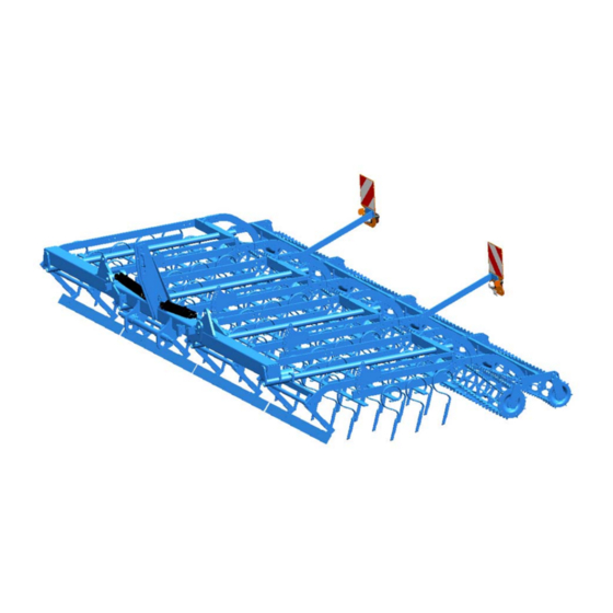
Design and function DESIGN AND FUNCTION Overview 1 Three-point tower 2 Frame 3 Tines 4 Working depth adjustment for tines 5 sprung multirail 6 Wheel track eliminator (not shown) 7 Roller 8 Hydraulic transport lock (not shown) 9 Guide wheels (not shown) 10 Drawbar 11 Lighting system... -
Page 34: Function
Design and function Function 5.2.1 Three-point tower The three-point tower with upper link pin and drawbar comply optionally with cate- gory 2, 3, 3N or 4N in accordance with ISO 730. The drawbar L2/Z2 complies with category 2. Drawbar L3/Z3 complies with category 3. Drawbar L2/Z3 complies with category 3N. -
Page 35: Working Depth Adjustment Of The Tines
Design and function 5.2.4 Working depth adjustment of the tines The working depth must be adjusted separately for each harrow field. 5.2.5 Wheel track eliminators The wheel track eliminators are placed in front of the tilling device. They are used for levelling and making the tractor wheel tracks friable, so facilitating consistent operation of the implement's tools. -
Page 36: Lighting System
Design and function 5.2.11 Lighting system The lighting system contributes significantly to increasing the safety of the imple- ment in road traffic. -
Page 37: Preparation Of The Tractor
Preparation of the Tractor PREPARATION OF THE TRACTOR Tyres The pressure - especially in the rear tractor tyres - must be equal. In heavy condi- tions it may be necessary to add wheel weights and/or water ballast. (See manu- facturer’s instructions). Lift Rods Adjust lift rods to equal length. -
Page 38: Required Hydraulic Equipment
Preparation of the Tractor Required hydraulic equipment The implement is supplied as standard with separate hydraulic connections for each consumer. The protective caps for the hydraulic connections are colour- coded and the hydraulic connections themselves are alphanumerically coded. For operation of the individual hydraulic devices listed below, the tractor must be equipped with the following double-acting control units: Trac- Single acting... -
Page 39: Three-Point Linkage
Preparation of the Tractor Three-point linkage Danger to life if three-point linkage category is too small If a drawbar or a top link pin is used with a category that is too small, these components may be overloaded and break. As a re- sult, the implement may fall down and injure or kill people in the DANGER immediate vicinity. - Page 40 Preparation of the Tractor For this implement, the only drawbars (1) and top link pins (2) approved are those listed in the table below and those that cor- respond to the category of the three-point linkage on the tractor. If they do not match, then either the tractor's three-point linkage or the implement's drawbar (1) and the top link pin (2) must be replaced with a suit-...
-
Page 41: Hydraulic System
Preparation of the Tractor Hydraulic system 6.7.1 Transport Lowering the three-point linkage CAUTION The device may be damaged if the three-point linkage of the trac- tor is lowered due to an incorrect setting or operation. For transport always switch the hydraulic system of the tractor to "position control". -
Page 42: Preparations On Implement
Preparations on implement PREPARATIONS ON IMPLEMENT Final assembly For transportation-specific reasons, the implement is not always delivered in a ful- ly-assembled condition. Use the implement only when the implement has been fully assembled and a functional check has been performed. -
Page 43: Attaching The Implement
Attaching the implement ATTACHING THE IMPLEMENT Risk of injury when coupling the device WARNING There is a risk of body parts being crushed between the tractor and device The tractor must be secured against unintentionally rolling away. Never actuate the hydraulic system of the tractor if there are people between the tractor and device. - Page 44 Attaching the implement Danger to life due to unsecured connection between lower link and drawbar If the connection between lower link and drawbar is not secured, the pintle of the drawbar may slip out. DANGER As a result, the implement may fall down and injure or kill people in the immediate vicinity.
-
Page 45: Coupling
Attaching the implement Coupling To couple the implement, switch the hy- draulic unit of the tractor's three-point linkage to position control. Drive the tractor backwards towards the implement until the tractor is in front of the implement and the arresting hooks of the lower links (2) can be coupled with the drawbar (3). - Page 46 »Parking supports, page 71« Korund 8/450 and Korund 8/600 Loosen the guide pin (8) and pull it out of the bore. Pull up the parking support (9). Secure the parking support (9) using a guide pin (8).
- Page 47 Attaching the implement Korund 8/750 The parking support adjusts itself auto- matically into the working position. Korund 8/900 Loosen the guide pin (8) and pull it out. Pull the parking support (9) out of the lower holder (10).
-
Page 48: Drawbar
Attaching the implement Drawbar The drawbar (1) can be mounted on the device at two heights = draw point posi- tions. The picture shows the drawbar (1) in the upper mounting position = low draw point. The bores (2) are used to hold the drawbar (1) in the lower mounting position = high draw point. -
Page 49: Upper Control Link
Attaching the implement Upper control link Risk of injury from unsecured upper control link pin If the upper control link pin is not secured, it may slip out or get CAUTION lost. As a result, the implement may fall down or be damaged. ... -
Page 50: Retracting/Extending The Side Parts
Retracting/extending the side parts RETRACTING/EXTENDING THE SIDE PARTS Risk of accident due to incorrect retraction of the side parts Incorrect retraction of the side parts will result in accidents if there are people in the slewing and folding area of the side part or if there are high-voltage lines in the slewing and folding area of the side DANGER parts. -
Page 51: General Information
Prior to retracting the device, ensure that the piston rods of the folding cylinders (1) as well as the frame (2) are free from soil. Korund 8/450 and Korund 8/600 Before retracting the side parts (3), lift out the device all the way. - Page 52 Retracting/extending the side parts Korund 8/750 and Korund 8/900 Before retracting the side parts (3), lift out the device all the way. Retract the side parts (3) of the imple- ment. This is done by operating the control unit in the retract position (1st pressure position).
-
Page 53: Extension
Retracting/extending the side parts Extension Risk of accident due to incorrect extension of the side parts Incorrect extension of the side parts will result in accidents if there are people in the hazardous areas of the side parts or if there are high-voltage lines in the slewing and folding area of the side parts. - Page 54 Retracting/extending the side parts Korund 8/450 and Korund 8/600 Before extending the side parts (3), lift out the implement all the way. Release the control unit of the tractor for the folding cylinders (2). Then switch the control unit to the ex- tend position (2nd pressure position).
-
Page 55: Driving On Public Highways
Driving on public highways DRIVING ON PUBLIC HIGHWAYS 10.1 General information A proper lighting system, identification and equipment must be on the implement, if it is to be transported on public roads. The country-specific valid laws and regu- lations pertaining to driving on public roads must be observed. 10.2 Preparation for driving on public roads Before commencing a journey on public roads, the following components and sa-... -
Page 56: Transport Dimensions
Driving on public highways 10.5 Transport dimensions Danger due to implement being raised too high WARNING The height of the retracted implement may be too high. This means there is an increased danger under bridges, driveways and high-voltage lines Ensure that the transport height of 4 m is not exceeded. ... -
Page 57: Operation
Operation OPERATION Read and follow the information in the section entitled "Safety and protection measures". CAUTION The implement may only be used, maintained and repaired by people who are familiar with it and who are aware of the haz- ards involved. -
Page 58: Working Depth Of Tines
Operation 11.1 Working depth of tines The working depth of the tines (1) is ad- justed by changing the position of the gui- de pins (2). The working depth can be adjusted in in- crements of approx. 1.5 cm. Insert the guide pin (2) in the desired ho- le of the adjustment device (3). -
Page 59: Multirail
Operation 11.2 Multirail 11.2.1 Height adjustment of the multirail The multirail shall level the soil and also the tractor tracks. Turn the spindle (2) of the multirail (1) clockwise as far as it will go. Now turn the spindle (2) back again by approx. -
Page 60: Changeover From "Grip" To "Drag" Position
Operation 11.2.2 Changeover from "Grip" to "Drag" position In light soil conditions, it is recommended to assemble the multirail (1) in drag posi- tion. Remove the bolts (3). Slightly loosen the bolts (4). Turn the multirail (1) by 45°. ... -
Page 61: Feeler Wheels
Operation 11.3 Feeler wheels Risk of injury due to unsecured feeler wheel If the guide pin and cam lever are simultaneously removed, the WARNING feeler wheel is no longer held in place and can slide downwards when unsecured. This can result in crushing and foot injuries. ... -
Page 62: Roller Harrow
The rollers control the implement at the working depth. Depending on the roller used, the soil is more or less recompacted or more or less crumbled. Roller type Korund 8 Toothed bar crumbler (double roller) ø 330/270 mm Tube toothed bar crumbler (double roller) ø 330/270 These rollers do not require any special adjustment measures. - Page 63 Operation Upper link The mounting position of the upper link exerts an influence on the lift height, the penetration characteristic and the roller pressure. The hydraulic unit of the three- point linkage on the tractor must be switched to the float position. Upper link position Feed...
- Page 64 Operation The lower the upper link is mounted on the implement's three-point tower, the greater the pressure load on the rollers – resulting in excellent penetration charac- teristic. The higher the upper link is mounted on the implement's three-point tower, the lower the pressure load on the rollers –...
- Page 65 Operation Upper link mounting position Risk of injury from unsecured upper link pin If the upper link pin is not secured, it may slip out or get lost. CAUTION As a result, the implement may fall down or be damaged. As a result, people in the immediate vicinity may be injured.
- Page 66 Operation Drawbar mounting position The mounting position of the drawbar (1) with unhitched implement can be changed as follows: Remove the nuts (3) on the bolts (4) of the two locking pieces (5). Pull the drawbar (1) as far as the middle out of the bores of the rail plates (6).
- Page 67 Operation Push the locking pieces (5) up to the rail plates (6). Ensure that the support surfaces (7) are positioned on the stop (8) of the rail pla- tes (6). Tighten the nuts (3) on the bolts (4) to a tightening torque of 197 Nm.
-
Page 68: Wheelmark Eradicator
Operation 11.5 Wheelmark eradicator Wheelmark eradicators (1) can be mounted on the carrier (2). The wheelmark eradicators can be relocated at the side and their depth adjusted. 11.5.1 Relocation at the side Adjust the wheelmark eradicator (1) to the bout of the tractor as follows: ... -
Page 69: Adjusting The Working Depth
Operation 11.5.2 Adjusting the working depth The wheelmark eradicators are set to approx. 5 cm deeper than the bout of the tractor. Adjust the working depth of the wheelmark eradicator as follows: Raise the implement to relieve the load- ing on the wheelmark eradicator (1). -
Page 70: Turning At The Headland
Operation 11.6 Turning at the headland DANGER Risk of damage to components If the implement is not fully raised, there is a danger that compo- nents may be damaged during an improper turn at the headland. Before turning at the headland the implement must be completely raised before turning-in to avoid any damage to the implement. -
Page 71: Uncoupling The Implement
Uncoupling the implement UNCOUPLING THE IMPLEMENT 12.1 Dismounting Place the device on solid and level ground. The device with 450 cm working width must only be parked in un- folded condition. Move the stands into the parking posi- tion. - Page 72 Uncoupling the implement Secure the tractor to prevent it from roll- ing away. Detach the electric cables. Detach the hydraulic hoses and push on the protective caps. Carefully drive the tractor away from the implement.
-
Page 73: Parking Supports
The Korund 8/750 K and 8/900 K may only be parked in folded condition if an im- plement for retracted parking has been coupled and moved into parking position. -
Page 74: Implement For Retracted Parking
12.3 Implement for retracted parking The Korund 8/750 K and 8/900 K are equipped with an additional implement that consists of a support frame and enables retracted parking even for these devices. The support frame supports itself on the frame of the central device field(s). -
Page 75: Switching Over To Different Share Systems
Switching over to different share systems SWITCHING OVER TO DIFFERENT SHARE SYSTEMS Danger due to unsupported device DANGER If the lifted out device is not secured on supports to prevent it from lowering, people underneath may be injured or killed. It is imperative to support the lifted out device if people are carry- ing out maintenance or service work in the hazardous area of the device. -
Page 76: After Both Sides Of The Share Are Worn
Switching over to different share systems 13.1.2 After both sides of the share are worn Replace the share when both sides of the share are worn. Loosen the nut on the bolt (2) and re- move the bolt. Remove the share (1). ... -
Page 77: Switching Off The Device
Switching off the device SWITCHING OFF THE DEVICE 14.1 Shutting down the device in an emergency In an emergency shut down the device via the tractor. Switch the tractor engine off. Remove the ignition key. Damage caused by improper storage of the device If incorrectly or improperly stored, the device may be damaged, CAUTION e.g. -
Page 78: Maintenance And Repairs
Maintenance and repairs MAINTENANCE AND REPAIRS 15.1 Special safety instructions 15.1.1 General Risk of injury when carrying out maintenance and repair work There is always the risk of injury when carrying out maintenance and repair work. WARNING Use suitable tools, suitable climbing aids, platforms and support elements. -
Page 79: Immobilise The Implement For Maintenance And Repairs
Maintenance and repairs 15.1.4 Immobilise the implement for maintenance and repairs Risk of accidents when tractor starts up Injuries may occur if the tractor starts moving during maintenance and repair work. Switch off the tractor engine before carrying out any work on the WARNING implement. -
Page 80: Working Under The Raised Device
Maintenance and repairs 15.1.7 Working under the raised device Risk of accident due to lowering and extending of compo- nents and devices It is extremely dangerous to work under raised or next to retracted WARNING components and devices. Always secure the tractor to prevent it from rolling away. Re- move the ignition key and secure the tractor to prevent it from being started up by unauthorised persons. -
Page 81: Environmental Protection
Maintenance and repairs Risk of accident due to tool slipping off If applying a large force, e.g. when loosening bolts, the tool may WARNING slip off. This may result in hand injuries on sharp-edged parts. Avoid applying a large force by using suitable auxiliary equip- ment (e.g. -
Page 82: Lubrication
Maintenance and repairs 15.3 Lubrication Eye injuries due to grease WARNING When lubricating the lubrication points, grease can escape be- tween components at high pressure and cause injury to the eyes. In case of injury, seek medical attention immediately. Wear protective clothing during lubrication, particularly goggles. ... -
Page 83: Lubrication Chart
Maintenance and repairs 15.3.1 Lubrication chart For all lubrication work use the high-grade grease Olistamoly 2 or an equivalent high-grade grease only. a) Pivot joints b) Feeler wheel Greasing of components Greasing of guide pins Greasing of piston rods using acid-free grease Blank surfaces of the levelling tines... -
Page 84: Overview Of Lubricating Points
Maintenance and repairs 15.3.2 Overview of lubricating points a) Pivot joints b) Feeler wheel... -
Page 85: Maintenance Intervals
The hydraulic hoses must be replaced at the latest 6 years after the date of manufacture. Use hydraulic ho- ses authorised by LEMKEN only. Safety equipment Check that the safety equipment functions properly. -
Page 86: Weekly Inspection
Maintenance and repairs 15.4.3 Weekly inspection Check What to do? Wheel nuts Check that all wheel nuts are tight and, if re- quired, retighten the wheel nuts to the appro- priate torque. Screw connections Retighten all other bolts and nuts on the device to the appropriate torque. -
Page 87: Tightening Torques
Maintenance and repairs 15.5 Tightening torques 15.5.1 General information Once loosened, secure self-locking nuts against self-loosening by exchanging the nuts with new self-locking nuts. by using safety washers. by using thread-locking compounds, such as Loctite. The following tightening torques refer to screw threaded fittings not specifically mentioned in these operating instructions. -
Page 88: Wheel Bolts And Wheel Nuts
Maintenance and repairs 15.5.2 Wheel bolts and wheel nuts Diameter / thread [Nm] 15.5.3 Bolts and nuts made of steel Strength category Diameter 10.9 12.9 [Nm*] [Nm*] [Nm*] 13,6 16,3 23,4 32,9 39,6 M 10 46,2 64,8 77,8 M 12 80,0 M 14 M 16... -
Page 89: Checking Connections To The Tractor
Maintenance and repairs 15.6 Checking connections to the tractor 15.6.1 Hydraulic connections Risk of accident due to spraying hydraulic fluid Fluid (hydraulic oil) escaping under high pressure can penetrate WARNING the skin and cause severe injuries. In case of injury, seek medical attention immediately. -
Page 90: Air Pressure Of Tyres
Maintenance and repairs 15.7 Air pressure of tyres WARNING Hazard due to incorrect air pressure Excessive air pressure in the tyres can cause the tyres to burst. Insufficient air pressure can cause overloading of the tyres. The following minimum and maximum permitted air pressures are approved, de- pending on the tyre size, the profile and the PR figure or the load index. -
Page 91: Technical Data
Technical data TECHNICAL DATA Korund 8 with Marathon tines Number of tines Weight with toothed bar crumbler 1.410 1.952 2.860 3.268 (double roller) approx. [kg] Transport width [cm] Height when device is parked ap- prox. [cm] Working width [cm] Centre of gravity distance approx. - Page 92 Technical data Korund 8 with Gare tines Number of tines Weight with toothed bar crumbler 1.374 1.904 2.800 3.196 (double roller) approx. [kg] Transport width [cm] Height when device is parked ap- prox. [cm] Working width [cm] Centre of gravity distance approx.
-
Page 93: Identification Plate
Identification plate IDENTIFICATION PLATE The identification plate (1) is situated on the front of the frame. -
Page 94: Noise, Airborne Sound
Noise, Airborne Sound NOISE, AIRBORNE SOUND The noise level of the implement does not exceed 70 dB (A) during work. NOTES As the version of equipment is depending from the order, the equipment of your implement and its description concerned may deviate in some cases. To ensure a continuously updating of the technical features, we reserve the right to modify the design, equipment and technique. -
Page 95: Index
Index INDEX Air pressure ......................88 Axle loads ......................22 Check Chains ....................... 35 Coupling ....................... 43 Drawbar ........................ 46 Extension......................51 Feeler wheels ....................... 59 Hydraulic equipment ..................... 36 MAINTENANCE ....................76 Power sources...................... 35 PREPARATION OF THE TRACTOR ..............35 REPAIRS......................
Need help?
Do you have a question about the Korund 8 and is the answer not in the manual?
Questions and answers