Table of Contents
Advertisement
Quick Links
Instruction book
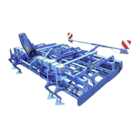
Seedbed combinations
System-Kompaktor S
and
System-Kompaktor K
Safety is our concern
Part-No. 175 3755
en-2/09.21
LEMKEN GmbH & Co. KG
Weseler Straße 5, D-46519 Alpen / Postfach 11 60, D-46515 Alpen
Telefon (0 28 02) 81-0, Telefax (0 28 02) 81-220
E-Mail: lemken@lemken.com, Internet: http://www.lemken.com
Advertisement
Table of Contents


Need help?
Do you have a question about the System-Kompaktor S Series and is the answer not in the manual?
Questions and answers