Table of Contents
Advertisement
Available languages
Available languages
Quick Links
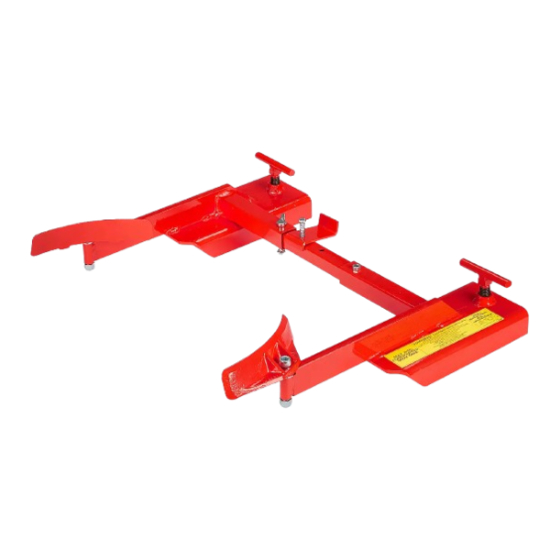
H-3343
SINGLE PLASTIC
DRUM GRABBER
TOOLS NEEDED
1/2" Socket Wrench
9/16" Socket Wrench
Fork Arm x 2
Adjustable
Tube x 1
1.
Slide compression spring onto 5/16 x 3" bolt and thread through barrel stop and hole B of adjustable tube.
Secure with jam nut. Use 1/2" socket wrench to tighten. (See Figure 1)
NOTE: For 55 gallon drum, barrel stop should extend toward back of unit. For 30 gallon drum, barrel stop
should extend toward front of unit. (See Figure 2)
Figure 1
5/16" Bolt
Adjustable
Tube
A
Jam Nut
PAGE 1 OF 12
1-800-295-5510
uline.com
1/2" Wrench
3/8" Allen
9/16" Wrench
Barrel Gripper x 2
Barrel Stop x 1
Compression
Spring
D E F
C
B
Barrel Stop
Wrench
PARTS
Socket Head Bolt x 2
Lynch Pin x 1
5/16 x 3" Bolt x 1
3/8-16 x 2" Bolt x 1
Compression
Gripper Spring x 2
Spring x 1
ASSEMBLY
Figure 2
Adjustable
Tube
Para Español, vea páginas 5-8.
Pour le français, consulter les pages 9-12.
1/2-13 x 3"
Lock Washer x 1
30 Gallon
Position
B
A
C
55 Gallon
Position
Barrel Stop
Jam Nut x 1
Hex Nut x 1
Locknut x 2
D E F
0424 IH-3343
Advertisement
Table of Contents

Subscribe to Our Youtube Channel
Related Manuals for U-Line H-3343


Summary of Contents for U-Line H-3343
- Page 1 Para Español, vea páginas 5-8. Pour le français, consulter les pages 9-12. H-3343 1-800-295-5510 uline.com SINGLE PLASTIC DRUM GRABBER TOOLS NEEDED 1/2" Socket Wrench 1/2" Wrench 3/8" Allen 9/16" Socket Wrench 9/16" Wrench Wrench PARTS 1/2-13 x 3" Jam Nut x 1...
- Page 2 ASSEMBLY CONTINUED 2. Insert adjustable tube into left-hand fork arm. Slide NOTE: For 55 gallon drum, insert lynch pin lock washer onto 3/8-16 x 2" bolt and thread through into hole D, E or F. Three holes available, hole A of adjustable tube. Secure with hex nut. Use depending on drum diameter.
-
Page 3: Installation
ASSEMBLY CONTINUED 6. Thread 1/2-13 x 3" socket head bolt through barrel Figure 9 gripper and fork arm. Secure with locknut. (See Figure 9) 1/2" Socket Head Bolt Repeat steps 4-6 for remaining barrel gripper and fork arm. Barrel Gripper 8. -
Page 4: Operation
OPERATION CLAMPING AND LIFTING THE DRUM Figure 12 Position drum grabber grippers under drum lip. Slowly lift and move drum to desired location. (See Figure 12) CAUTION! Use only on poly drums with at least a 3/16" top lip. SAFETY CAUTION! For use on poly drums only. -
Page 5: Herramientas Necesarias
H-3343 800-295-5510 uline.mx TRANSPORTADOR SENCILLO DE TAMBOS DE PLÁSTICO HERRAMIENTAS NECESARIAS Llave de Dado de 1/2" Llave de 1/2" Llave Allen de 3/8" Llave de Dado de 9/16" Llave de 9/16" PARTES 2 Pernos de Cabeza 1 Tuerca Hueca de 1/2-13 x 3"... - Page 6 CONTINUACIÓN DE ENSAMBLE 2. Inserte el tubo ajustable en el brazo para horquilla NOTA: Para tambo de 55 galones, inserte izquierdo. Deslice la rondana de seguridad sobre el pasador tipo clavija por los orificios D, E el perno de 3/8-16 x 2" y atorníllelo a través del o F.
-
Page 7: Instalación
CONTINUACIÓN DE ENSAMBLE 6. Enrosque el perno de cabeza hueca de 1/2-13 x 3" Diagrama 9 a través del sujetador de tambos y el brazo para horquilla. Asegure con la contratuerca. Perno de Cabeza (Vea Diagrama 9) Hueca de 1/2" Repita los pasos 4 a 6 para el sujetador de tambos y el brazo para horquilla restantes. - Page 8 FUNCIONAMIENTO SUJETAR Y LEVANTAR EL TAMBO Figure 12 Coloque el transportador de tambos por debajo del reborde del tambo. Levante lentamente y mueva el tambo a la ubicación deseada. (Vea Diagrama 12) ¡PRECAUCIÓN! Compatible solo con tambos de plástico con un mínimo de reborde superior de 3/16".
-
Page 9: Outils Requis
H-3343 1-800-295-5510 uline.ca PORTE-BARIL SIMPLE POUR BARIL EN PLASTIQUE OUTILS REQUIS Clé à douille de 1/2 po Clé de 1/2 po Clé Allen de 3/8 po Clé à douille de 9/16 po Clé de 9/16 po PIÈCES Boulon à tête creuse de Contre-écrou x 1... - Page 10 MONTAGE SUITE 2. Insérez le tube réglable dans le bras de fourche REMARQUE : Pour les barils de 55 gallons, gauche. Faites glisser la rondelle de blocage sur le insérez la goupille dans le trou D, E ou F. Trois boulon 3/8-16 x 2 po, puis faites-le passer à travers trous sont disponibles, en fonction du diamètre le trou A du tube réglable.
- Page 11 MONTAGE SUITE 6. Vissez le boulon à tête creuse de 1/2-13 x 3 po à Figure 9 travers le préhenseur de baril et le bras de fourche. Fixez le tout avec un écrou freiné. (Voir Figure 9) Boulon à tête creuse de 1/2 po Répétez les étapes 4 à...
- Page 12 FONCTIONNEMENT PRÉHENSION ET SOULÈVEMENT DU BARIL Figure 12 Positionnez les préhenseurs de baril sous le rebord du baril. Soulevez et déplacez lentement le baril à l'endroit souhaité. (Voir Figure 12) MISE EN GARDE! N'utilisez le porte-baril que sur des barils en polyéthylène avec un rebord supérieur d'au moins 3/16 po.
Need help?
Do you have a question about the H-3343 and is the answer not in the manual?
Questions and answers