Table of Contents
Advertisement
Available languages
Available languages
Quick Links
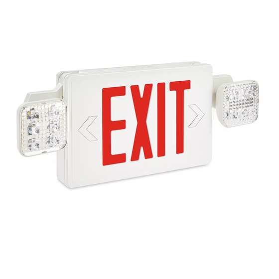
H-9045, H-9275
HARD-WIRED EXIT SIGN
TOOLS NEEDED
Flathead Screwdriver
CAUTION! When using electrical equipment,
always follow basic safety precautions, including:
• Do not use outdoors.
• Do not mount near gas or electric heaters.
• Do not let power cords touch hot surfaces.
• Use caution when servicing batteries to avoid
possible shorting.
• Mount in locations and at heights where it
will not readily be subjected to tampering by
unauthorized personnel.
• Use of accessories not recommended by the
manufacturer may cause an unsafe condition.
BACK MOUNTING
1.
Unit comes with EXIT panels on front and back.
Remove back EXIT panel and replace with back
plate. Drill 1/4" holes into oblong knock outs on back
plate that correspond to junction box holes to be
used. (See Figure 1)
Figure 1
Oblong Knock Outs
EXIT Panel
PAGE 1 OF 9
1-800-295-5510
uline.com
Phillips Screwdriver
INSTALLATION
Junction
Wire Nuts
Box
Back Plate
Plastic
Housing
Diffuser
Snap-in
Directional Arrow
SAFETY
• Do not use this equipment for anything other
than intended use.
• Before wiring to AC service, turn off AC power
at fuse or circuit breaker.
• Disconnect AC power and unplug battery
before servicing.
• Only use specified lamps in the fixture.
NOTE: Battery in unit may not be fully charged.
After AC service is supplied to unit, let battery
charge for at least 24 hours before performing
any tests.
2. Feed transformer input leads through center hole of
back plate and make the proper connections.
(See Figures 2-3)
NOTE: If using 120VAC, connect black and white
leads to building utility.
NOTE: If using 277VAC, connect orange and
white leads to building utility.
NOTE: In some cases, not all leads will be used.
Cap off unused wire.
120VAC
Connect black and white
leads to building utility.
Cap Unused
Orange Wire
Figure 2
Para Español, vea páginas 4-6.
Pour le français, consulter les pages 7-9.
277VAC
Connect orange and white
leads to building utility.
Cap Unused
Black Wire
Figure 3
0221 IH-9045
Advertisement
Table of Contents

Related Manuals for U-Line H-9045


Summary of Contents for U-Line H-9045
- Page 1 Para Español, vea páginas 4-6. Pour le français, consulter les pages 7-9. H-9045, H-9275 1-800-295-5510 uline.com HARD-WIRED EXIT SIGN TOOLS NEEDED Flathead Screwdriver Phillips Screwdriver SAFETY CAUTION! When using electrical equipment, • Do not use this equipment for anything other always follow basic safety precautions, including: than intended use.
-
Page 2: Ceiling Mounting
INSTALLATION CONTINUED 3. Feed excess wire into junction box and secure back 5. Feed excess wire into junction box and align holes in plate to junction box. (See Figure 1) canopy with holes in crossbar. Use screws supplied to tighten canopy to crossbar so canopy is securely 4. - Page 3 INSTALLATION CONTINUED 3. Attach sign to canopy by inserting canopy into sign at 5. Feed excess wire into junction box and align holes an angle. Twist to secure. (See Figure 9) in canopy to crossbar so that canopy is securely fastened and tight against the ceiling.
-
Page 4: Herramientas Necesarias
H-9045, H-9275 800-295-5510 uline.mx SEÑALAMIENTO "EXIT" CON CABLEADO HERRAMIENTAS NECESARIAS Desarmador Plano Desarmador de Cruz SEGURIDAD ¡PRECAUCIÓN! Cuando utilice equipos eléctricos, • No utilice este equipo para otra cosa que no siempre siga las precauciones de seguridad sea su uso previsto. - Page 5 CONTINUACIÓN DE INSTALACIÓN 3. Inserte el excedente de alambre en la caja de NOTA: Si usa 120VAC, conecte las puntas conexiones y asegure la placa posterior a esta. negras y blancas a la instalación del edificio. (Vea Diagrama 1) NOTA: Si usa 277VAC, conecte las puntas 4.
- Page 6 CONTINUACIÓN DE INSTALACIÓN 2. Abra la cubierta "EXIT". (Vea Diagrama 6) Inserte las 4. Inserte las puntas de entrada del transformador puntas de entrada del transformador a través del por el orificio central y realice las conexiones orificio superior asegurándose de fijar el alambre a adecuadas.
-
Page 7: Outils Requis
H-9045, H-9275 1-800-295-5510 uline.ca ENSEIGNE DE « EXIT » CÂBLÉE OUTILS REQUIS Tournevis à tête plate Tournevis cruciforme SÉCURITÉ MISE EN GARDE! Lors de l'utilisation d'appareils • N'utilisez pas cet équipement à d'autres fins électriques, vous devez toujours respecter les que celles prévues. - Page 8 INSTALLATION SUITE 3. Acheminez le surplus de fils dans la boîte de 4. Acheminez les fils d'entrée du transformateur jonction et fixez la plaque à la boîte de jonction. à travers le trou central, puis procédez aux (Voir Figure 1) branchements adéquats.
- Page 9 INSTALLATION SUITE FIXATION AU PLAFOND 3. Fixez l'enseigne à la hotte en insérant la hotte en biais dans l'enseigne. Tournez pour fixer. (Voir Figure 9) Reliez la barre croisée à la boîte de jonction. Placez la barre croisée de façon à ce que la longue lame Hotte touche la boîte de jonction.
Need help?
Do you have a question about the H-9045 and is the answer not in the manual?
Questions and answers
Do you offer an outdoor rated remote head to add to this Emergency light package