Advertisement
Quick Links
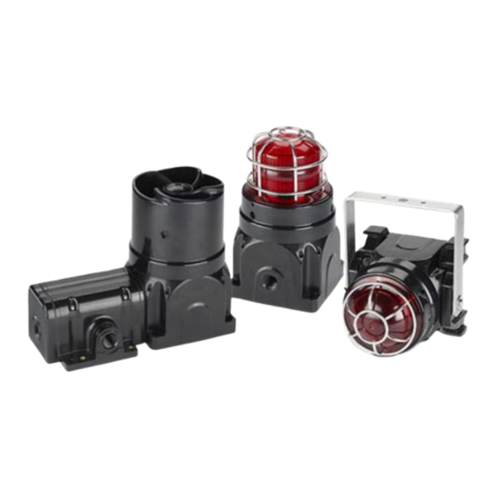
G-Series
Modular Platform Audible and Visual
Product Family
850000454 Rev A1 0122
Limited Warranty: This product's limited warranty can be found at www.fedsig.com/SSG-Warranty.
WARNING - Failure to follow all safety precautions and instructions may result in property damage, serious injury, or
death to you or others.
MESSAGES TO INSTALLERS AND USERS
important to follow all instructions shipped with the products. This device is to be installed by a trained electrician who
is thoroughly familiar with the National Electric Code and will follow the NEC guidelines as well as local codes.
The selection of the mounting location for the device, its controls and routing of the wiring is to be accomplished
under the direction of the Facilities Engineer and the Safety Engineer. Listed below are some other important safety
instructions and precautions you should follow.
•
Read and understand instructions before installing or operating equipment.
•
Do not connect this unit to the system when power is on.
•
All effective warning speakers produce loud sounds which may cause, in certain situations, permanent hearing
loss. You should take appropriate precautions such as wearing hearing protection.
•
After installation, test the sound system to ensure proper operation.
•
All effective warning speakers produce loud sounds, which may cause, in certain situations, permanent hearing
loss. The device should be installed far enough away from potential listeners to limit their exposure while still
maintaining its effectiveness.
•
The OSHA Code of Federal Regulations 1910.95 Noise Standard provides guidelines which may be used regarding
permissible noise exposure levels.
•
Show these instructions to your Safety Engineer and then file them in a safe place and refer to them when
maintaining and/or reinstalling the unit.
•
After installation and completion of initial system test, a program of periodic testing of this device must be
established. Refer to NFPA 72G, local Fire Codes and the authority having jurisdiction for this information.
•
Consult the authority having jurisdiction in your area regarding the proper use and installation of this product.
SHOCK HAZARD - To avoid electrical shock hazards, do not connect wires when power is applied.
Scope
This document is intended to be used by internal technical support, sales personnel, and outside design and engineering
resources responsible for the planning of future G-Series product installations. It documents what feature options are
available for various product configurations, and details field wire termination for various applications. This document
is intended to supplement the instruction manuals for the various signals. (Reference the Applicable and/or Referenced
Documents section for specific document identification.)
People's lives depend on your safe installation of our products. It is
Advertisement

Subscribe to Our Youtube Channel
Related Manuals for Federal Signal Corporation G Series


Summary of Contents for Federal Signal Corporation G Series
- Page 1 G-Series Modular Platform Audible and Visual Product Family 850000454 Rev A1 0122 Limited Warranty: This product’s limited warranty can be found at www.fedsig.com/SSG-Warranty. WARNING - Failure to follow all safety precautions and instructions may result in property damage, serious injury, or death to you or others.
- Page 2 Applicable and/or Referenced Documents The documents listed below pertain in some way to the design, construction, sourcing, testing, or performance of the G-Series Audible and Visual Product Family: Instruction Manuals • 25500186 Instruction Manual, G-Series LED (G-LED) • 25500187 Instruction Manual, G-Series Sounder (G-SND) •...
- Page 3 "Ex de" G-Series LED "Ex d" G-Series Sounder G-Series Dual "de d" (Increased Safety) (Flameproof) Increased Safety Combination Unit Audible Products Amplified Loudspeaker Feature Set Multi-voltage input with loop-out terminal positions • AC or DC (selection based on field termination location) •...
- Page 4 SW1 Position Description 1 120 Amplifier is configured to operate at 110 Vac-120 Vac 2 230 Amplifier is configured to operate at 220 Vac-240 Vac (Factory Set) JP1 Position Description 1 0.8 Amplifier is configured to amplify standard line-level audio (0.8 V 2 2.8 Amplifier is configured to amplify ECHO product-level audio (2.8 V Wiring the G-Series Amplified Loudspeaker "Ex de"...
- Page 5 Figure 6 Figure 7 230 Vac Amplified Loudspeaker Vdc Amplified Loudspeaker Wiring with Power Loop-Out Wiring with Power Loop-Out Installing and Wiring the Increased Safety "Ex de" Housing Figure 8 Figure 9 Figure 10 Ex de" Amplified Loudspeaker "Ex de" Terminal Block Volume and Input Level Jumper Connection Locations...
- Page 6 Figure 11F Figure 12 Vac Dual-Unit with Amplified Loudspeaker (AL) 24 Vdc Dual-Unit with Amplified Loudspeaker (AL) Wiring Locations Wiring Locations The G-Series Amplified Loudspeaker includes a volume potentiometer (located on the transformer PCBA) that allows for field adjustment of the output level (see Ill 1-10 on page 10). While the G-Series Amplified Loudspeaker is shipped from the factory at full volume, field reduction of the output level might be required or desired in certain applications.
- Page 7 Figure 15 Figure 16 Figure 17 Amplified Loudspeaker (AL) and Dual "de d" Terminal Block Volume and Input Level Jumper Unspecified Device (UD) (Common Between Devices) (AL Only) Connection Locations Description L1/+ Input Power In (“Hot/L1/DC+”) L2/- Input Power Return (“Neutral/L2/DC-”) Earth Ground Termination Point L3/Alt+ Secondary Power In (“Hot/L3/DC+”)
- Page 8 If a nearby product requires AC or DC power loop-through, the G-Series Dual "de d" Terminal Chamber supports power loop-out field termination. As the terminal chamber provides two (2) M20 entries for cable passage, at least one entry must be dedicated for incoming conductors. Federal Signal recommends verifying that the application wiring requirements and cable conductor count allow for input cabling to occupy a single entry before architecting a loop-in/ loop-out topology.
- Page 9 Connection Locations Description “1” Available Taps: 7 W/5 W/2 W or 0.5 W/0.3 W/0.1 W “2” Available Taps: 10 W/7 W or 0.7 W/0.5 W “3” Available Taps: 15 W/5 W or 1.0 W/0.3 W “4” Available Taps: 15 W/10 W/2 W or 1.0 W/0.7 W/0.1 W JP4 Position Description High Power...
- Page 10 Figure 27 Figure 28 Loudspeaker Wired for Remote Tapping Loudspeaker Wired for Remote Tapping (High Power, 70 V or 100 V (Low Power, 70 V or 100 V The G-Series Loudspeaker allows for loop-in and loop-out connections through "Ex d" housing, where connecting another G-Series Loudspeaker assembly or loop-back supervision is desired or required.
- Page 11 JP4 Position Description High Power The high-power taps are available on the terminal block (Factory Set) Low Power The low-power taps are available on the terminal block Wiring the G-Series Loudspeaker "Ex de" terminal chamber requires two (2) conductors terminated at the desired power locations.
- Page 12 Connection Locations Description L1/+ (Reserved for secondary device) L2/- (Reserved for secondary device) Alt1 (Reserved for secondary device) Alt2 Available Taps: 15 W/10 W or 1.0 W/0.7 W (Position “D”) Alt3 Available Taps: 15 W or 1.0 W (Position “C”) Alt4 Available Taps: 10 W or 0.7 W (Position “B”) G-Series combination devices require wiring practices dependent on the devices combined.
- Page 13 Sounder Feature Set Multi-voltage input with loop-out terminal positions • AC or DC (selection based on field termination location) • 120 Vac or 230 Vac (selector switch) 15 On-board tones • Single-tone selection with operation on power-up • Remote tone selection of all 15 on-board tones possible •...
- Page 14 Wiring the G-Series Sounder "Ex d" housing to play a single tone on AC or DC power requires three (3) conductors for input power (with an earth conductor). Wiring the G-Series Sounder "Ex d" housing for remote tone selection on AC power requires a minimum of six (6) conductors;...
- Page 15 Figure 46 Figure 47 230 Vac Sounder Single-Tone Wiring Locations 24 Vdc Sounder Single-Tone Wiring Locations Figure 48 Figure 49 230 Vac Sounder with Full Remote Selection 24 Vdc Sounder with Full Remote Selection The G-Series Sounder includes a volume potentiometer (located on the transformer PCBA) that allows for field adjustment of the output level (see Ill 3-3 on page 23).
- Page 16 Figure 50 Figure 51 230 Vac Single-Tone Sounder Wiring with Power Loop-Out 24 Vdc Single-Tone Sounder Wiring with Power Loop-Out Remote tone selection is limited by the number of available conductors entering the "Ex d" housing. The tables that follow help identify tones available with limited numbers of conductors, based on the type of G-Series Sounder product. To use the table: Identify two tones for remote selection.
- Page 17 G-Series AC Sounder "Ex d" Housing Products, Limited to 6 or Fewer Conductors Installation and Maintenance Instructions Federal Signal signaling.fedsig.com...
- Page 18 G-Series DC Sounder "Ex d" Housing Products, Limited to 4 or Fewer Conductors G-Series Modular Platform Federal Signal signaling.fedsig.com...
- Page 19 Installing and Wiring the Increased Safety "Ex de" Housing Figure 52 Figure 53 Figure 54 "Ex de" Sounder "Ex de" Terminal Block Level Adjust and Tone Selection Connection Locations Description L1/+ Input Power In (“Hot/L1/DC+”) L2/- Input Power Return (“Neutral/L2/DC-”) Alt1 Earth Ground Termination Point Alt2...
- Page 20 Wiring the G-Series Sounder "Ex de" terminal chamber for a single-tone on AC or DC power requires three (3) conductors for input power (with an earth conductor). The G-Series Sounder setup and wiring within the "Ex d" housing is configured at the factory to match the input power ordered, and tone “C”...
- Page 21 Figure 55 Figure 56 230 Vac Sounder Single-Tone Wiring Locations 24 Vdc Sounder Single-Tone Wiring Locations The G-Series Sounder "Ex de" terminal chamber can be wired for limited remote tone selection. For AC products, the remote tone select line SEL is made available, as well as tone select lines T3 and T4. For DC products, T2, T3, and T4 are made available.
- Page 22 Access to tone selection pins (T#) marked in requires device rewiring. For example, consider the following tone selection of “Tone Low” and “Pulse Low” in an AC Sounder application: This tone can be selected using a total of six conductors (three for AC power and ground, one for SEL, and two for tone select), and the tone select wires should be landed at T4 (shown with an “x”...
- Page 23 G-Series AC Sounder "Ex de" Terminal Chamber Products, Limited to 6 or Fewer Conductors Installation and Maintenance Instructions Federal Signal signaling.fedsig.com...
- Page 24 G-Series DC Sounder "Ex de" Terminal Chamber Products, Limited to 4 or Fewer Conductors G-Series Modular Platform Federal Signal signaling.fedsig.com...
- Page 25 If the desired tones are accessible with the number of conductors available, but the tone selection positions are shown for one or more of the positions, the G-Series Sounder "Ex d" housing terminal block will need to be rewired. To rewire the terminal block, locate the T1-T4 terminal locations on the sounder PCBA. Note the factory locations for bushing wires “5”...
- Page 26 Figure 63 Figure 64 G-Series Sounder Single-Tone Wiring Locations G-Series Sounder with Limited Remote Selection with Power Loop-Out and Power Loop-Out Installing and Wiring Dual "de d" Combination Unit Housings Figure 65 Figure 66 Figure 67 Sounder (SD) and Unspecified Device (UD) Dual "de d"...
- Page 27 Figure 68 Figure 69 Dual-Unit (SD) Configuration Dual-Unit (SD) with Power Loop-In/Loop-Out G-Series combination devices allow for loop-in and loop-out connections through the "Ex de" terminal chamber, for connecting another G-Series combination unit, or another G-Series product. As with the other devices, if a nearby product requires AC or DC power loop-through, the G-Series "Ex de"...
- Page 28 Figure 70 Figure 71 Figure 72 Sounder (SD) and Unspecified Device (UD) Dual "de d" Terminal Block Level Adjust and Tone Selection (Common between devices) (Sounder Only) Xenon Strobe Beacon Feature Set Model-specific voltage input with loop-out terminal positions • 110/120 Vac with loop-out •...
- Page 29 Figure 77 Figure 78 AC LED Beacon Wiring Locations DC LED Beacon Wiring Locations The G-Series LED Beacon is capable of displaying eight discrete visual patterns at three selectable speeds. These selections must be made during or prior to installation. (I.e., they are not remotely changeable.) To adjust the LED pattern selection: Locate the pattern switch on the 20000199 PCBA.
- Page 30 If a nearby product requires AC or DC power loop-through, the G-Series "Ex d" housing supports power loop-out field termination. As the "Ex d" housing provides two (2) M20 entries for cable passage, at least one entry must be dedicated for incoming conductors.
- Page 31 Figure 86 Figure 87 LED Beacon Wiring Locations (AC or DC) LED Beacon with Power Loop-Out (AC or DC) Installing and Wiring Dual "de d" Combination Unit Housings Figure 88 Figure 89 Figure 90 LED Beacon (LB) and Terminal Block (Common between devices) LED Pattern Select and Speed Dial Unspecified Device (UD) (LED Device)
- Page 32 Figure 91 Figure 92 Dual-Unit (LB) Wiring Locations Dual-Unit (LB) with Power Loop-Out Xenon Strobe Beacon Feature Set Model-specific voltage input with loop-out terminal positions • 110/120 Vac with loop-out • 220-240 Vac with loop-out • 24 Vdc with loop-out Cable Entries •...
- Page 33 Wiring the G-Series Xenon Strobe Beacon "Ex d" housing for AC or DC power requires three (3) conductors for input power (with an earth conductor). Depending on the model ordered, the Xenon Strobe Beacon will accept either 110 Vac, 50/60 Hz; or 220 Vac, 50/60 Hz. The DC Xenon Strobe Beacon will accept 24 Vdc. Figure 96 Figure 97 AC Xenon Strobe Beacon Wiring Locations...
- Page 34 Wiring an AC or DC G-Series combination unit Dual "de d" terminal chamber with a Xenon Strobe Beacon (SB) requires three (3) conductors are required for input power (with an earth conductor), leaving three (3) terminal locations open for the unspecified device (UD). The product setup and wiring within the "Ex d" housing is configured at the factory to-order; the only installation requirement for device operation is field wire termination to the proper terminal block position.
- Page 35 If a nearby product requires AC or DC power loop-through, G-Series combination Dual "de d" terminal chamber supports power loop-out field termination. As the Dual "de d" terminal chamber provides two (2) M20 entries for cable passage, at least one entry must be dedicated for incoming conductors. Federal Signal recommends verifying the application wiring requirements and cable conductor count allow for input cabling to occupy a single entry before architecting a loop-in/ loop-out topology.
- Page 36 Additional translations available at signaling.fedsig.com Traducciones adicionales disponibles en signaling.fedsig.com Customer Support 1-800-344-4634+1-708-534-4756, iordersup@fedsig.com Technical Support 1-800-755-7621+1-708-587-3587, signalsupport@fedsig.com signaling.fedsig.com © Copyright 2015-2022 Federal Signal Corporation All product names or trademarks are properties of their respective owners. G-Series Modular Platform Federal Signal signaling.fedsig.com...
Need help?
Do you have a question about the G Series and is the answer not in the manual?
Questions and answers