Federal Signal Corporation Vision SLR Series Installation Maintenance And Service Manual
Light bar
Hide thumbs
Also See for Vision SLR Series:
- Installation maintenance and service manual (48 pages) ,
- Installation maintenance and service manual (32 pages)

Related Manuals for Federal Signal Corporation Vision SLR Series


Summary of Contents for Federal Signal Corporation Vision SLR Series
- Page 1 Vision SLR Light Bar ® Installation, Maintenance, and Service Manual 2562540 REV. C4 0820 Printed in U.S.A. © Copyright 2015-2020 Federal Signal Corporation...
- Page 2 A copy of this limited warranty can also be obtained by written request to Federal Signal Corporation, 2645 Federal Signal Drive, University Park, IL 60484, email to info@fedsig.com or call +1 708-534-3400.
-
Page 3: Table Of Contents
Contents Safety Messages..........................6 Safety Message to Installers and Service Personnel of Warning Lights ...........6 Safety Message to Operators of Warning Light Equipment ..............9 An Overview of the Vision SLR Light Bar ................... 11 LED Lights and Colors ........................... 11 LED Flash Rates and Positions ........................ - Page 4 Getting Repair Service ..........................51 Ordering Replacement Parts ........................52 Tables Table 1 Dimensions ............................12 Table 2 Light Specifications ........................... 12 Table 3 Electrical Specifications ........................12 Table 4 SW2 DIP switch settings in the Serial Interface Module ............16 Table 5 Control wires from the Serial Interface Module .................
- Page 5 Figure 18 SignalMaster removed from the light bar ................. 43 Figure 19 SignalMaster disassembled ......................44 Figure 20 Controller connectors ........................45 Figure 21 Controller location beneath light bar cover ................46 Figure 22 Locations of watertight connectors ..................46 Figure 23 Secondary lock mechanism in the plug and receptacle .............
-
Page 6: Safety Messages
Safety Messages Safety Messages For your safety, read and understand this manual thoroughly before installing, operating, and servicing the Vision SLR light bar. The safety messages presented in this section and throughout the manual are reminders to exercise extreme care at all times. - Page 7 Safety Messages • A light system is a high current system. In order for the system to function properly, a separate negative (–) connection and positive (+) connection must be made. All negative connections should be connected to the negative battery terminal and a suitable fuse should be installed on the positive battery terminal connection as close to the battery as possible.
- Page 8 Safety Messages • If a vehicle seat is temporarily removed, verify with the vehicle manufacturer if the seat needs to be recalibrated for proper airbag deployment. • Before mounting any components, check the manual to be sure that the component you are installing is suitable for use in that area of the vehicle. Many components are not suitable for use in the engine compartment or other extreme environmental exposure areas.
-
Page 9: Safety Message To Operators Of Warning Light Equipment
Safety Messages • After installation and testing are complete, provide a copy of these instructions to instructional staff and all operating personnel. • File these instructions in a safe place and refer to them when maintaining and/or re- installing the product. Failure to follow these precautions may result in property damage, serious injury, or death. - Page 10 Safety Messages • Suction cup mounting is for temporary applications only. The unit should be removed from the window and stored securely when not in use. Temperature changes and sunlight can cause suction cups to lose holding power. Periodically check the unit to be sure the suction cups have a firm grip on the mounting surface.
-
Page 11: An Overview Of The Vision Slr Light Bar
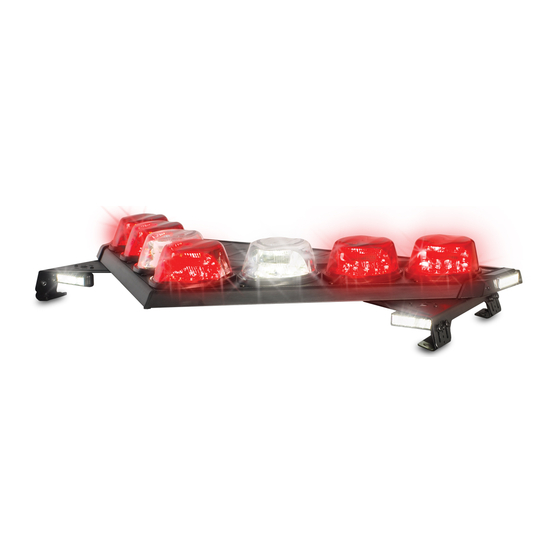
An Overview of the Vision SLR Light Bar An Overview of the Vision SLR Light Bar The Vision SLR is a rotating LED light bar, employing fixed LED boards and rotating Solaris S2 reflectors. V-shaped construction lets the Vision SLR warning system maximize light warning efficiency at crucial intersection angles. -
Page 12: Controller Options
An Overview of the Vision SLR Light Bar Controller Options Flash patterns are controlled through the light bar’s CAT5 communication cable. The cable connects to the Serial Interface Module (Part Number 8583446), the Federal Signal Six-Button Serial Controller (Part Number 8623133), the Three-Button Serial Controller (Part Number 8623141), or the SmartSiren Series Platinum System or the ®... -
Page 13: Preparing The Vision Slr For Installation
Preparing the Vision SLR for Installation Preparing the Vision SLR for Installation Taking the preparatory steps in this section before mounting and wiring the light bar to a vehicle will help ensure that your installation is fast, easy, and error free. In addition to instructions for quick testing the light bar, this section also has instructions for changing default settings and flash patterns with the Serial Interface Module. -
Page 14: Figure 1 Serial Interface Module Connections For Programming
Preparing the Vision SLR for Installation The numbers in the steps below refer to the wires in Figure 1. To connect the Vision SLR to the battery and Serial Interface Module: 1. To supply power to the light bar, use a fully-charged 12-volt automotive battery with terminal lugs. -
Page 15: Selecting External Signalmaster Control
Preparing the Vision SLR for Installation Selecting External SignalMaster Control The Interface Module comes factory-set for the INTERNAL SignalMaster option. (See ® “Selecting Internal SignalMaster Control [Factory Default].”) With EXTERNAL control the Interface Module drives each SignalMaster head independently via an external Federal Signal SignalMaster controller or the SS2000SM Series Siren. -
Page 16: Table 4 Sw2 Dip Switch Settings In The Serial Interface Module
Preparing the Vision SLR for Installation Table 4 SW2 DIP switch settings in the Serial Interface Module Switch Setting Switch Down Number (OFF) (ON) Function Front/Rear LEDs cut off (turn off) when 12 Vdc is applied their ✔ control wires Front/Rear LEDs enable (turn on) when 12 Vdc is applied to their ✔... -
Page 17: Entering Program Mode
Preparing the Vision SLR for Installation Entering Program Mode To switch the module from Operation Mode to Program Mode: 1. Unplug the 24-pin harness from the Serial Interface Module. 2. On the Serial Interface Module, move Switch 6 on SW2 to the down (ON) position. 3. -
Page 18: Figure 2 Connectors And Switches On The Serial Interface Module
Preparing the Vision SLR for Installation SW2 DIP Switch Settings in the Serial Interface Module For the location of SW2, see Figure 2. For the SW2 switch settings for programming the light bar, see Table 4 on page 16. Figure 2 Connectors and switches on the Serial Interface Module SW1 Button for Selecting Flash Patterns J3 Connector for Serial... - Page 19 Preparing the Vision SLR for Installation 3. Remove 12 Vdc from the Mode 3 control wire. Mode 2 To set a Mode 2 flash pattern: 1. Apply 12 Vdc (+BAT) to the Mode 2 control wire (blue/white) from the Serial Interface Module to display the assigned pattern.
-
Page 20: Exiting Program Mode
Preparing the Vision SLR for Installation • 8-SECOND TIMEOUT activated by +BAT: momentary 12 Vdc turns on the Intersection flash pattern for 8 seconds. To change from HIGH to TAP II or 8-SECOND TIMEOUT: 1. Unplug the 24-pin harness from the Serial Interface Module. 2. -
Page 21: Wiring The Vision Slr In The Vehicle
Wiring the Vision SLR in the Vehicle 2. On the Serial Interface Module, move SW2 Switch 6 to the up (OFF) position. 3. Plug the 24-pin harness into the Serial Interface Module. Wiring the Vision SLR in the Vehicle Before proceeding, ensure that the light bar has been installed on the vehicle roof in accordance with the instructions included with the mounting kit. - Page 22 Wiring the Vision SLR in the Vehicle AIRBAG DEPLOYMENT: Do not install equipment or route wiring in the deployment path of an airbag. Failure to observe this warning will reduce the effectiveness of the airbag or potentially dislodge the equipment, causing serious injury or death.
-
Page 23: Connecting Power To The Light Bar
Wiring the Vision SLR in the Vehicle Connecting Power to the Light Bar NOTE: The VSLR can draw up to 350 mA in standby. To avoid battery drain, wire the light bar to an ignition activated switch capable of 30 A. NOTE: Plan the location of the wire-routing hole in the vehicle roof so that the power and communication cables do not have tight bends and have some slack to allow disconnection on removal. - Page 24 Wiring the Vision SLR in the Vehicle To mount the Serial Interface Module and make the power connections: 1. Use the Serial Interface Module as a template and scribe four drill-position marks at the selected mounting location. Mounting centers are 2 by 5.95 inches (5.08 by 15.11 cm).
-
Page 25: Wiring The Serial Interface Module
Wiring the Vision SLR in the Vehicle Figure 3 Relay-isolating devices with large filter capacitors Relay Strobe Supply Control Lead (12 Vdc Signal Activated) +12 Vdc Fuse* 290A6562 *Fuse Amperage Depends on Amperage of Devices Wiring the Serial Interface Module FUSE ELECTRICAL SOURCES: Always fuse current/voltage sources with a fuse connected near the power source. - Page 26 Wiring the Vision SLR in the Vehicle Priority Modes 1, 2, and 3 To activate a priority mode, apply 12 Vdc (+BAT) to a mode control wire. Mode 3 (black/red) overrides Mode 2 (blue/white), and Mode 2 overrides Mode 1 (blue). You can program one of the flash patterns in the light bar to each Mode input.
- Page 27 Wiring the Vision SLR in the Vehicle Takedown Lights When 12 Vdc (+BAT) is applied to the Takedown control wire (white/black), the takedown LEDs turn on. Takedown overrides Flash Takedown/Alley and Front Cutoff. Scene Light, Left and Scene Light, Right To use this function with the Serial Interface Module, place SW2 Switch 3 in the Module in the down position (ON).
-
Page 28: Table 7 Signalmaster Control Wires And Warning Patterns
Wiring the Vision SLR in the Vehicle The Serial Interface Module is factory-set for the Internal SignalMaster option. Internal operation uses the light bar’s built-in SignalMaster controller to generate directional warning patterns. With internal operation, an external SignalMaster controller is not needed. -
Page 29: Figure 6 Signalmaster Control Functions Wired To 12 Vdc For Internal Serial Interface Module Control
Wiring the Vision SLR in the Vehicle Figure 6 SignalMaster control functions wired to 12 Vdc for internal Serial Interface Module control J1 Cable to Power (+12 Vdc) Serial Interface Module Black/Red Mode 3 Blue/White Mode 2 Blue Mode 1 Red/White Steady Burn (Or Scene Light, Left with SW-2 Switch 3... -
Page 30: Figure 7 Signalmaster Control Functions Wired To 12 Vdc For Internal Serial Interface Module Control
Wiring the Vision SLR in the Vehicle Figure 7 SignalMaster control functions wired to 12 Vdc for internal Serial Interface Module control J1 Cable to Power (+12 Vdc) Serial Interface Module Black/Red Mode 3 Blue/White Mode 2 Blue Mode 1 Red/White Steady Burn (Or Scene Light, Left With Sw-2 Switch 3... -
Page 31: Figure 8 Typical Connections With A Signalmaster Controller (External Control)
Wiring the Vision SLR in the Vehicle Figure 8 Typical connections with a SignalMaster controller (external control) Wht/Red Red/Grn Blu/Red Org/Grn Grn/Blk/Wht Blu (Mode 1) Blu/Wht (Mode 2) Blk/Red (Mode 3) Wht/Blk (Td) Grn/Blk (L. Al) Org/Red (R. Al) Installation, Maintenance, and Service Manual Federal Signal www.fedsig.com... -
Page 32: Figure 9 Typical Connections With A Sw400Ss Switch Module (Internal Control)
Wiring the Vision SLR in the Vehicle Figure 9 Typical connections with a SW400SS Switch Module (internal control) +12 V Red (Left) Grn (Center) Grn/Blk/Wht (Right) Org/Grn (Warn1) Org (Warn2) Wht/Red (Fast) Blu (Mode 1) Blu/Wht (Mode 2) Blk/Red (Mode 3) Wht/Blk (Td) Grn/Blk (L. -
Page 33: Figure 10 Typical Connections With A Smartsiren Model Ss2000Sm Controller
Wiring the Vision SLR in the Vehicle Figure 10 Typical connections with a SmartSiren Model SS2000SM controller Wht (1) Brn (2) Grn/Blk/Wht Grn (3) Org/Gn) Orn (4) Prp (5) Blu/Red Gra (6) Red/Grn Yel (7) Wht/Red Blu (8) None (9) Red+ (10) Blk−... -
Page 34: Figure 11 Typical Connections With A Non-Signalmaster Controller
Wiring the Vision SLR in the Vehicle Figure 11 Typical connections with a non-SignalMaster controller Blu (Mode 1) Blu/Wht (Mode 2) Blk/Red (Mode 3) Wht/Blk (Td) Grn/Blk (L. Al) Org/Red (R. Al) Vision SLR Light Bar Federal Signal www.fedsig.com... -
Page 35: Figure 12 Typical Connections With A Pa640 Controller
Wiring the Vision SLR in the Vehicle Figure 12 Typical connections with a PA640 controller Blk/Red (Mode 3) Red/Blk (Fl Tkd/al) Blu/Wh T (Mode 2) Blu (Mode 1) Wht/Blk (Td) Grn/Blk (L.Al) Org/Red (R.Al) Installation, Maintenance, and Service Manual Federal Signal www.fedsig.com... -
Page 36: Maintaining And Servicing The Vision Slr
Maintaining and Servicing the Vision SLR Maintaining and Servicing the Vision SLR This section describe how to maintain and service the Vision SLR light bar. Establishing a regular maintenance and inspection schedule extends the life of the light bar and ensures safety. For service, support, or replacement parts, contact the Federal Signal Service Department at 1-800-433-9132, 7 a.m. -
Page 37: Replacing A Dome
Maintaining and Servicing the Vision SLR Replacing a Dome The light bar domes filter the LED lights and protect the LED and circuitry. If a dome is damaged, it must be replaced. Tool required: • T25 Torx driver Removing a Dome To remove a light bar dome: 1. -
Page 38: Replacing A Pod
Maintaining and Servicing the Vision SLR Installing a Dome To install a dome: DO NOT FORCE THE DOME DOWNWARD: If there is resistance to the dome dropping into position on the base, do not force it downward. To avoid damaging the dome, ensure that the dome hook is properly centered with the mating recess in the pod base so that it drops down from the vertical position. -
Page 39: Replacing An Led Alley Light
Maintaining and Servicing the Vision SLR Figure 14 Pods 1 and 5 rotated counterclockwise for removal #10-32 Torx Shoulder Screw Rotate Clockwise Rotate Counter-Clockwise to the Stopping Point to the Stopping Point Indicated by Pod 5 Indicated by Pod 1 290A7701 Installing a Pod To install a pod:... -
Page 40: Figure 15 Alley Light Removal: Exploded View
Maintaining and Servicing the Vision SLR Removing an LED Alley Light To remove an alley light: 1. Disconnect all power to the light bar at the battery or at the light bar. 2. Use a T20 Torx driver to remove the two 8-32 Torx screws and the alley light cap. 3. -
Page 41: Removing And Replacing The Light Bar Cover
Maintaining and Servicing the Vision SLR 5. Insert the two 1/4"-20 Torx screws into the inner holes on the alley light mount and through the aluminum extrusion of the light bar base. Tighten the screws. 6. Reinstall the alley light cap. 7. -
Page 42: Removing And Reinstalling The Signalmaster
Maintaining and Servicing the Vision SLR Reinstalling the Light Bar Cover To reinstall the cover: 1. Place the cover into position on the light bar. DO NOT OVERTIGHTEN: To avoid damaging the light bar, do not overtighten the screws/nuts. 2. Insert and tighten the two 10-32 Torx screws and the six 8-32 Torx screws. 3. -
Page 43: Servicing The Signalmaster
Maintaining and Servicing the Vision SLR Reinstalling the SignalMaster Assembly To reinstall the SignalMaster assembly: ® 1. Plug the SignalMaster cable into the SML connector on the light bar controller. 2. Place the assembly into position in the rear of the light bar. Center the holes of the SignalMaster assembly extrusion over the holes in the aluminum extrusion on the rear of the light bar. -
Page 44: Figure 19 Signalmaster Disassembled
Maintaining and Servicing the Vision SLR Disassembling the SignalMaster To disassemble the SignalMaster ® 1. Remove the light bar cover as described in “Removing the Light Bar Cover” on page 41. 2. Remove the SignalMaster assembly as described in “Removing the SignalMaster”on page 42. -
Page 45: Replacing The Light Bar Controller
Maintaining and Servicing the Vision SLR Replacing the Light Bar Controller The light bar controller, which controls the flash patterns and auxiliary lights, is a configured option. If a light bar problem cannot be traced to a PCB, a wiring connection, or the vehicle battery (Table 8 on page 49), the problem may lie with the controller. -
Page 46: Quick Disconnect Option For Power And Cat5
Maintaining and Servicing the Vision SLR Figure 21 Controller location beneath light bar cover 8-32 Keps Nuts (4) CONTROLLER 290A6611 Quick Disconnect Option for Power and CAT5 An optional detachable weather-proof connector at the bottom of the light bar on the passenger side enables you to quickly disconnect both power and communication together without opening the light bar. -
Page 47: Figure 23 Secondary Lock Mechanism In The Plug And Receptacle
Maintaining and Servicing the Vision SLR Figure 23 Secondary lock mechanism in the plug and receptacle CPA (connector position assurance) Locking Latch Locking Ramp Receptacle Plug Disconnecting a Cable at the Light Bar (Quick Disconnect Option) To disconnect the power or CAT5 cable: 1. - Page 48 Maintaining and Servicing the Vision SLR 3. Pull the connectors apart. Reconnecting a Cable at the Light Bar (Quick Disconnect Option) To reconnect the power or CAT5 cable: 1. Firmly push the connectors together until you feel them snap together and you hear a click.
-
Page 49: Troubleshooting The Light Bar
Maintaining and Servicing the Vision SLR Troubleshooting the Light Bar This section provides troubleshooting assistance for common problems. If you have any questions left unanswered, call the Federal Signal Service Department at 1-800- 433-9132, 7 a.m. to 5 p.m., Monday through Friday (CT). Table 8 Troubleshooting tips Problem Corrective Action... -
Page 50: Quick Testing The Vision Slr With The Light Bar Test
Maintaining and Servicing the Vision SLR Problem Corrective Action The light bar has a ✔ Ensure that the connections on the Serial Interface Module are kept delayed response to separate from strobe supplies. being shut off ✔ Check all the ground connections, especially on the Serial Interface Module. -
Page 51: Testing The Steady Burn Leds (Hotfoot Only)
(default setting). 2. Remove 12 Vdc from the Mode and Steady Burn control wires. Getting Technical Support and Service For technical support and service, please contact: Service Department Federal Signal Corporation Phone: 1-800-433-9132 Email: empserviceinfo@fedsig.com www.fedsig.com Getting Repair Service The Federal Signal factory provides technical assistance with any problems that cannot be handled locally. -
Page 52: Ordering Replacement Parts
Getting Technical Support and Service Ordering Replacement Parts To order replacement parts, call Customer Support at 1-800-264-3578, 7 a.m. to 5 p.m., Monday through Friday (CT) or contact your nearest distributor. Table 9 Replacement parts Description Part Number PCB Assembly, SignalMaster (Configured) Contact Service PCB Assembly, Controller Contact Service...
Need help?
Do you have a question about the Vision SLR Series and is the answer not in the manual?
Questions and answers