
Related Manuals for Federal Signal Corporation Integrity Series


Summary of Contents for Federal Signal Corporation Integrity Series
- Page 1 Integrity Light Bar Installation, Maintenance, and Service Manual 25500063 REV. B2 0820 © Copyright 2014-2020 Federal Signal Corporation...
- Page 2 Limited Warranty This product is subject to and covered by a limited warranty, a copy of which can be found at www.fedsig.com/SSG-Warranty. A copy of this limited warranty can also be obtained by written request to Federal Signal Corporation, 2645 Federal Signal Drive, University Park, IL 60484, email to info@fedsig.com or call +1 708-534-3400.
-
Page 3: Table Of Contents
Contents Safety Messages..........................6 Safety Message to Installers and Service Personnel of Warning Lights ...........6 Safety Messages to Operators of Federal Signal Sound/Light Systems ..........9 An Overview of the Integrity Light Bar ..................10 ® LED Lights, Colors, and Flash Patterns ....................10 Electrical System ............................ - Page 4 Low Power or Optional AutoDim ......................24 Ignition ............................... 25 SignalMaster Connections........................25 Maintaining and Servicing the Integrity ..................35 Installing the Filler Strips (Sponge Cords) ....................35 Cleaning the Light Bar Lens ........................36 Removing and Reinstalling the Light Bar Lens..................36 Removing the Lens ..........................
- Page 5 Tables Table 1 Dimensions ............................11 Table 2 Light Specifications ........................11 Table 3 Electrical and Temperature ......................11 Table 4 SW-2 DIP Switch Settings ......................14 Table 5 Control wires from the Serial Interface Module ..............15 Table 6 Switch settings for INTERSECTION operation ..............18 Table 7 Cross reference for controller leads (external Serial Interface Module control) ..
-
Page 6: Safety Messages
Safety Messages Safety Messages For your safety, read and understand this manual thoroughly before installing, operating, and servicing the Integrity light bar. The safety messages presented in this section ® and throughout the manual are reminders to exercise extreme care at all times. Read and understand the safety instructions and keep them close at hand for reference. - Page 7 Safety Messages • Never attempt to install aftermarket equipment that connects to the vehicle wiring, without reviewing a vehicle wiring diagram available from the vehicle manufacturer. Ensure that your installation will not affect vehicle operation or mandated safety functions or circuits. Always check the vehicle for proper operation after installation. •...
- Page 8 Safety Messages • The service life of light bulbs and strobes tubes will be shortened if the glass portion is touched during installation. Use gloves when handling these components. If the glass portion has been touched, clean the glass carefully with isopropyl alcohol.
-
Page 9: Safety Messages To Operators Of Federal Signal Sound/Light Systems
Safety Messages Safety Messages to Operators of Federal Signal Sound/Light Systems People’s lives depend on your safe operation of Federal Signal products. It is important to read and follow all instructions shipped with the products. Listed below are some other important safety instructions and precautions you should follow: •... -
Page 10: An Overview Of The Integrity Light Bar
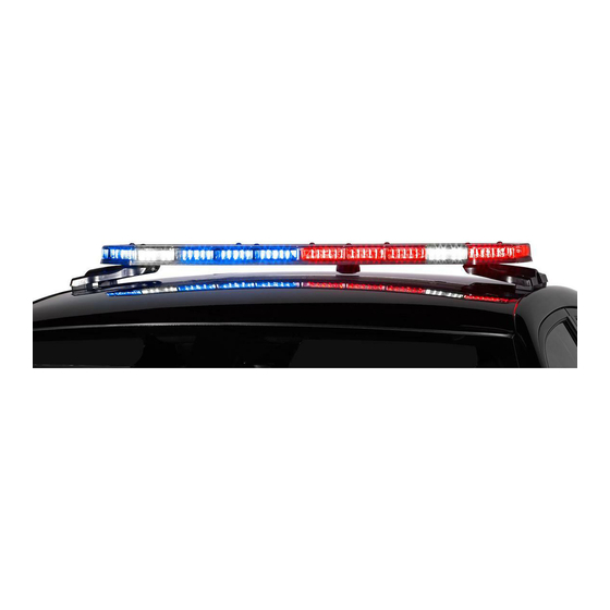
An Overview of the Integrity® Light Bar An Overview of the Integrity Light Bar ® The Integrity light bar is a single-level LED light bar with ROC (Reliable On-Board Circuitry) and Solaris LED technologies. ROC eliminates approximately 85 percent of ®... -
Page 11: Product Specifications
An Overview of the Integrity® Light Bar Product Specifications Operating and technical specifications for the Integrity light bar are listed in this section by model. Table 1 Dimensions Model Integrity44 Integrity51 SIze (L x W x H) 43.7 x 9.7 x 1.96 inches 51.3 x 9.7 x 1.96 inches (111.0 x 246.4 x 5.0 cm) (130.3 x 9.7 x 5.0 cm) -
Page 12: Reprogramming The Light Bar
Reprogramming the Light Bar Reprogramming the Light Bar HEAVY OBJECT: Use lifting aids and proper lifting techniques when removing or replacing this product. Failure to heed this warning may cause personal injury. Carefully unpack the light bar assembly and any other products included in the shipment. Inspect them for damage that may have occurred during shipping. -
Page 13: Switch Settings And Connectors On The Serial Interface Module
Reprogramming the Light Bar Figure 1 Electrical connections for reprogramming the light bar Driver Passenger Side Side Fuse 40 A Maxi Power Line (Red) CAT5 Com. Ground Power Line (Black) Cable (Gray) Serial Interface – Module 12 Vdc Vehicle Battery Black Wire Fuse Black/White Wire... -
Page 14: Selecting External Signalmaster Control
Reprogramming the Light Bar Figure 2 DIP switch settings in Serial Interface Module SW1 Button for Selecting Flash Patterns J3 Connector for Serial Cable from Light Bar SW2 DIP Switches (See Table 5 on page 15) J1 Connector For 24-Conductor Cable Supplied With Serial Interface Module Programming Header for Cloning Flash Patterns from Vehicle to Vehicle (See the... -
Page 15: Selecting Internal Signalmaster Control (Factory Default)
Reprogramming the Light Bar Selecting Internal SignalMaster Control (Factory Default) To select Internal SignalMaster control: 1. Unplug the 24-pin harness from the Serial Interface Module. 2. Move Switch 4 on SW-2 to the down (ON) position. 3. Plug the 24-pin harness into the Serial Interface Module. Identifying the Control Wires for Flash Patterns This section describes how to program flash patterns by applying 12 Vdc to the control wires in the 24-pin harness of Serial Interface Module. -
Page 16: Entering Program Mode
Reprogramming the Light Bar Entering Program Mode To switch the module from Operation Mode to Program Mode: 1. Unplug the 24-pin harness from the Serial Interface Module. 2. On the Serial Interface Module, move Switch 6 on SW-2 to the down (ON) position. 3. - Page 17 Reprogramming the Light Bar 3. Remove 12 Vdc from the MODE 2 control wire. Mode 1 1. Apply 12 Vdc (+BAT) to the MODE 1 control wire (blue) from the Serial Interface Module to display the assigned pattern. 2. On the Serial Interface Module, press and release the SW-1 button until the pattern you want appears on the light bar.
-
Page 18: Exiting Program Mode
Reprogramming the Light Bar Table 6 Switch settings for INTERSECTION operation SW-2 Operational Settings HIGH (+BAT maintained) OFF (up) OFF (up) TAP II (+BAT, push on/push off ) ON (down) OFF (up) 8-SECOND TIMEOUT (activated by +BAT) OFF (up) ON (down) Front/Rear Enable or Cutoff The operational setting for FRONT/REAR ENABLE or CUTOFF must be programmed after MODE and INTERSECTION. -
Page 19: Wiring The Integrity Light Bar In The Vehicle
Wiring the Integrity Light Bar in the Vehicle Wiring the Integrity Light Bar in the Vehicle Before proceeding, ensure that the light bar has been installed on the vehicle roof in accordance with the instructions included with the mounting kit. Depending on the type of vehicle and mounting system feature, there are two options available for installing the light bar to the roof of the vehicle: hook-on mounting or permanent mounting. -
Page 20: Connecting Power To The Light Bar
Wiring the Integrity Light Bar in the Vehicle 10. Do not coil excess wire. Leave a drain loop for servicing. 11. After drilling holes for wires, de-burr them, smooth sharp edges, and insert grommets to protect the wires from chafing. 12. -
Page 21: Installing The Serial Interface Module
Wiring the Integrity Light Bar in the Vehicle Figure 3 Power and cable connections Driver Passenger Side Side Fuse 40 A Max (+BAT) Power Line (Red) CAT5 Com. (NEG-) Ground Power Line (Black) Cable (Gray) Serial Interface – Module 12 Vdc Vehicle J1 Connector Battery... -
Page 22: Figure 4 Relay For Isolating Devices With Large Filter Capacitors
Wiring the Integrity Light Bar in the Vehicle DRILLING PRECAUTIONS: Before drilling holes, check the area into which you plan to drill to ensure that you do not damage vehicle components. All drilled holes should be de-burred and all sharp edges should be smoothed. Additionally, all exterior drilled holes must be sealed with Motorcraft seam sealer T-A-2-B or equivalent to prevent the potential exposure to carbon monoxide or other potentially harmful fumes. -
Page 23: Wiring The Serial Interface Module
Wiring the Integrity Light Bar in the Vehicle Wiring the Serial Interface Module This section is an overview of default settings that are activated when connecting LED and Mode control wires to 12 Vdc (+BAT). The basic light functions of the light bar must be controlled by an installer-supplied control head. -
Page 24: Intersection
Wiring the Integrity Light Bar in the Vehicle Intersection When 12 Vdc (+BAT) is applied to the Intersection control wire (blue/black) and a Mode control wire, it turns on the Intersection pattern. When 12 Vdc is removed, the light bar returns to its previous state. -
Page 25: Ignition
Wiring the Integrity Light Bar in the Vehicle If the light bar is equipped with AutoDim, it will automatically dim at night as long as the controller is not in MODE 3. Once MODE 3 is removed, the light bar will again dim to 50 percent of full brightness. -
Page 26: Figure 5 Signalmaster 331105 Controller (External Signalmaster Control)
Wiring the Integrity Light Bar in the Vehicle Table 7 Cross reference for controller leads (external Serial Interface Module control) 24-Pin Harness from SignalMaster SS2000SM* the Serial Interface Wire Wire Module (Figure 5) (Figure 6) White White (1) Green Brown Brown (2) Green/Black/White Green... -
Page 27: Figure 7 Signalmaster Control Functions Wired To Ground For External Sim Control
Wiring the Integrity Light Bar in the Vehicle Table 8 SignalMaster control wires and warning patterns (internal SM control)) Warning Pattern Control Wires Description (with 8-head example) LEFT Rear LEDs flash from right to left CENTER OUT Green Rear LEDs flash from center out to both sides RIGHT Green/Black/White Rear LEDs flash from left to right WARN 1... - Page 28 Wiring the Integrity Light Bar in the Vehicle Figure 7 SignalMaster control functions wired to ground for external Serial Interface Module control J1 Cable to Power (+12 Vdc) Serial Interface Module Black/Red Mode 3 Mode 2 Blue/White Blue Mode 1 Steady Burn Red/White (or Scene Light, Left with SW-2 Switch 3...
-
Page 29: Figure 8 Signalmaster Control Functions Wired To 12 Vdc For Internal Control
Wiring the Integrity Light Bar in the Vehicle Figure 8 SignalMaster control functions wired to 12 Vdc for Internal control J1 Cable to Power (+12 Vdc) Serial Interface Module Black/Red Mode 3 Blue/White Mode 2 Blue Mode 1 Red/White Steady Burn (or Scene Light, Left with SW-2 Switch 3 down [ON] in the Serial Interface Module) Blue/Black... -
Page 30: Figure 9 Typical Connections With A Signalmaster Controller (External Control)
Wiring the Integrity Light Bar in the Vehicle Figure 9 Typical connections with a SignalMaster controller (external control) WHT/RED RED/GRN BLU/RED ORG/GRN GRN/BLK/WHT BLU (MODE 1) BLU/WHT (MODE 2) BLK/RED (MODE 3) WHT/BLK (TD) GRN/BLK (L. AL) ORG/RED (R. AL) Integrity Light Bar Federal Signal www.fedsig.com... -
Page 31: Figure 10 Typical Connections With A Model Sw400Ss Switch Module (Internal Control)
Wiring the Integrity Light Bar in the Vehicle Figure 10 Typical connections with a Model SW400SS Switch Module (internal control) +12V RED (LEFT) GRN (CENTER) GRN/BLK/WHT (RIGHT) ORG/GRN (WARN1) ORG (WARN2) WHT/RED (FAST) BLU (MODE 1) BLU/WHT (MODE 2) BLK/RED (MODE 3) WHT/BLK (TD) GRN/BLK (L. -
Page 32: Figure 11 Typical Connections With A Smartsiren Model Ss2000Sm Controller
Wiring the Integrity Light Bar in the Vehicle Figure 11 Typical connections with a SmartSiren Model SS2000SM controller WHT (1) BRN (2) GRN/BLK/WHT GRN (3) ORG/GN) ORN (4) PRP (5) BLU/RED GRA (6) RED/GRN YEL (7) WHT/RED BLU (8) NONE (9) RED+ (10) BLK- (11) Integrity Light Bar... -
Page 33: Figure 12 Typical Connections With A Non-Signalmaster Controller
Wiring the Integrity Light Bar in the Vehicle Figure 12 Typical connections with a non-SignalMaster controller BLU (MODE 1) BLU/WHT (MODE 2) BLK/RED (MODE 3) WHT/BLK (TD) GRN/BLK (L. AL) ORG/RED (R. AL) Installation, Maintenance, and Service Manual Federal Signal www.fedsig.com... -
Page 34: Figure 13 Typical Connections With A Model Pa640 (Pa64000) Controller
Wiring the Integrity Light Bar in the Vehicle Figure 13 Typical connections with a Model PA640 (PA64000) controller Integrity Light Bar Federal Signal www.fedsig.com... -
Page 35: Maintaining And Servicing The Integrity
Maintaining and Servicing the Integrity Maintaining and Servicing the Integrity This section describes how to maintain and service the Integrity light bar. Establishing a regular maintenance and inspection schedule extends the life of the light bar and ensures safety. For service, support, or replacement parts, contact the Federal Signal Service Department at 1-800-433-9132, 7 am to 5 pm, Monday through Friday (CT). -
Page 36: Cleaning The Light Bar Lens
Maintaining and Servicing the Integrity Cleaning the Light Bar Lens CRAZING/CLEANING SOLUTIONS: The use of cleaning solutions, such as strong detergents, solvents, and petroleum products, can cause crazing (cracking) of the light bar lens and reflectors. To clean the reflectors, use a soft, damp cloth. To clean the lens, use a soft cloth and a solution of water and a mild detergent. -
Page 37: Reinstalling The Lens
Maintaining and Servicing the Integrity 4. Inspect the O-rings and the lip seal for deformation, brittleness, cuts, or tears. To maintain watertightness, replace a questionable O-ring or seal. 5. Inspect the lens for cracks, crazing (hairline cracks), and other defects. Figure 15 Locations of the barrel nuts in lens (numbers indicate tightening sequence) FSC-66 FSC-67... -
Page 38: Removing A Pcb
Maintaining and Servicing the Integrity Figure 16 Locations of ROC PCBs END PCB INTERMEDIATE INTERMEDIATE END PCB CONTROLLER 290A7481 Tool required: • T27 Torx driver Removing a PCB To remove a PCB: 1. Disconnect all power to the light bar. 2. -
Page 39: Resetting The Controller
Maintaining and Servicing the Integrity Resetting the Controller These instructions explain how to reset the light bar controller after you install a service replacement board or if the light heads operate erratically. For the ] light bar to operate correctly, the controller stores information about which LED colors it controls. Resetting the light bar controller may be necessary if you replace the controller board or if the LEDs flash erratically. -
Page 40: Troubleshooting The Light Bar
Maintaining and Servicing the Integrity Troubleshooting the Light Bar This section provides troubleshooting assistance for common problems. If you have any questions left unanswered, call the Federal Signal Service Department at 1-800-433-9132, 7 am to 5 pm, Monday through Friday (CT). Table 9 Troubleshooting tips Problem Corrective Action... - Page 41 Maintaining and Servicing the Integrity Problem Corrective Action The light bar has a delayed response to • Ensure that the connections on the Serial Interface Module are kept being shut off separate from strobe supplies. • Check all the ground connections, especially on the Serial Interface Module.
-
Page 42: Getting Technical Support And Service
Getting Technical Support and Service Getting Technical Support and Service For technical support and service, please contact: Service Department Federal Signal Corporation Phone: 1-800-433-9132 Email: empserviceinfo@fedsig.com www.fedsig.com Getting Repair Service The Federal Signal factory provides technical assistance with any problems that cannot be handled locally. -
Page 43: Ordering Replacement Parts
Getting Technical Support and Service Ordering Replacement Parts This section contains a partial list of replacement parts. To order replacement parts, call the Federal Signal Service Department at 1-800-433-9132, 1-708-534-3400, 7 am to 5 pm., Monday through Friday (Central Time) or contact your nearest distributor. Table 10 Replacement parts Description Part Number... - Page 44 2645 Federal Signal Drive University Park, Illinois 60484-3167 www.fedsig.com Customer Support Police/Fire-EMS: 800-264-3578 • +1 708 534-3400 Work Truck: 800-824-0254 • +1 708 534-3400 Technical Support 800-433-9132 • +1 708 534-3400...
Need help?
Do you have a question about the Integrity Series and is the answer not in the manual?
Questions and answers