
Related Manuals for Federal Signal Corporation Navigator Lightbar


Summary of Contents for Federal Signal Corporation Navigator Lightbar
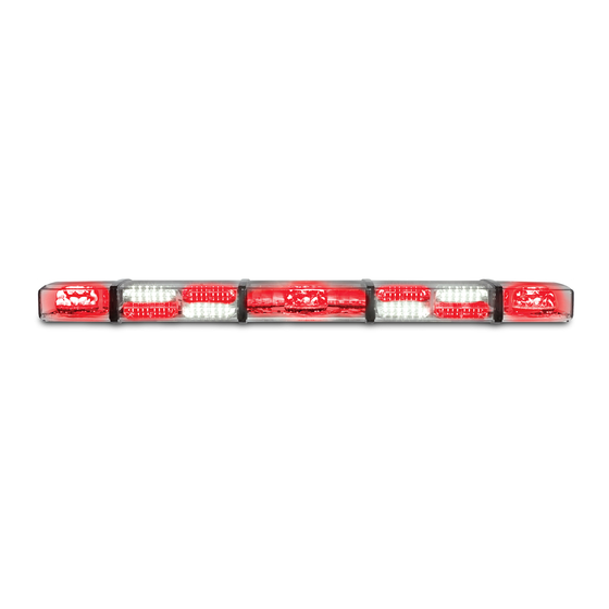
- Page 1 Navigator Lightbar ® Installation, Operation, and Service Instructions 25500145 Rev. C0 0716 Printed in U.S.A.
-
Page 3: Table Of Contents
Navigator Lightbar Contents Safety Messages to Installers Warning Light Equipment ..............5 Safety Messages to Operators ......................7 Overview of the Lightbar ........................8 Solaris LED Reflector Technology ........................8 LED Rotating Lights ............................8 QuadraFlare LED Stationary Lights ......................... 8 Control Options ..............................8 Mount Options .............................. - Page 4 Navigator Lightbar Figures Figure 1 Flash pattern pushbutton on control board discrete-wired Navigator ............ 11 Figure 2 Central control board with switches off (down) ..................13 Figure 3 All-rotator power distribution board ....................... 14 Figure 4 Wire functions for 4-conductor cable (10-inch all stationary)..............17 Figure 5 Wire functions for 10-conductor cable ....................
-
Page 5: Safety Messages To Installers Warning Light Equipment
Navigator Lightbar Safety Messages to Installers Warning Light Equipment People’s lives depend on your proper installation and servicing of Federal Signal products. It is important to read and follow all instructions shipped with this product and the original product. Listed below are some other... - Page 6 Navigator Lightbar During Installation and Service • DO NOT get metal shavings inside the product. Metal shavings in the product can cause the system to fail. If drilling must be done near the unit, place an ESD approved cover over the unit. Inspect the unit after mounting to be sure there are no shavings present in or near the unit.
-
Page 7: Safety Messages To Operators
Navigator Lightbar • Scratched or dull reflectors, mirrors or lenses will reduce the effectiveness of the lighting system. Avoid heavy pressure and use of caustic or petroleum based products when cleaning the lighting system. Replace any optical components that may have been scratched or crazed during system installation. -
Page 8: Overview Of The Lightbar
Navigator’s options and overall flexibility can be used on fire apparatus and command/fleet vehicles. A Navigator lightbar can be configured to have all stationary LED heads, all rotating heads, or a mix of both stationary LED heads with rotating heads. The Navigator lightbar comes in multiple lengths from 10 inches to 87 inches for a consistent look across an entire fleet of vehicles. -
Page 9: Mount Options
Navigator Lightbar Mount Options Hook Mount Kit: Z8653134 Permanent Mount Kit: Z8653134-01 Flat Surface Mount Kit:* Z8653178-1, Z8653178-2, Z8653178-3 4-inch Riser Mount:* Z806501522-2, Z806501522-4 Vehicle Specific Mounting Options: HKB-(model). Contact the factory for updated vehicle hook-mount options *Kit options depend on the length of the lightbar. -
Page 10: Programming The Lightbar
Navigator Lightbar Programming the Lightbar Although the Navigator lightbar is configured and programmed at the factory, you may want to change the default flash patterns before you install the lightbar. Flashing Modes The number of flashing modes varies by bar length. You can select a flash pattern for each available mode from the lightbar’s internal library of flash patterns For a list of patterns, refer to Table 3 and Table 4 starting on page 11. -
Page 11: Figure 1 Flash Pattern Pushbutton On Control Board Discrete-Wired
Navigator Lightbar Figure 1 Flash pattern pushbutton on control board discrete-wired Navigator Pattern selection button Channel A rotors are located in the outer positions of the lightbar. Channel B rotators are located in the inner positions. Denotes default flash pattern Power leads connector for Mode 1. -
Page 12: Table 4 Navigator Flash Patterns: 45 In, 53 In, And 60 In Serial-Controlled/Discrete Lightbar
Navigator Lightbar Table 4 Navigator flash patterns: 45 in, 53 in, and 60 in serial-controlled/discrete lightbar No. Description Rotator Solid head alternating quad flashes 90 RPM Split-head shuffle/triple flash 90 RPM Rotate heads clockwise around 90 RPM Alternating solid-head quad flash – amber 90 RPM Decelerating solid-head flash –... -
Page 13: Changing The Features On A 45-Inch, 53-Inch And 60-Inch Navigator
Figure 2 Central control board with switches off (down) Table 5 Functions of SW4 VBAT/SW If the Navigator lightbar is controlled by a Convergence Network control head, the lightbar can power the control head through the CAT5 cable. To enable this feature set the switch to ON. -
Page 14: Determining The Mounting Location And Wire Routing
Navigator Lightbar Figure 3 All-rotator power distribution board PMTH1 20000160 FEDERAL SIGNAL CORPORATION UNIVERSITY PARK, IL PMTH2 J16 CONNECTOR: J15 CONNECTOR: +12 Vdc POWER ALLEY LIGHTS FLOOD LIGHTS REAR LIGHT CUTOFF WHITE LIGHT LEGENDS FOR LIGHTHEAD JUMPERS J8 TO J14... -
Page 15: Wiring The Navigator In The Vehicle
Navigator Lightbar INSTALLATION PRECAUTIONS: The warning system and/or two-way radio system may operate improperly if a two-way radio antenna installed on or within 18 inches of the lightbar. Before permanently installing the lightbar or a two-way radio antenna, test the warning system and two-way radio system. DO NOT install a two-way radio antenna on the lightbar. -
Page 16: Connecting Power To The Lightbar
Navigator Lightbar Table 6 Cabling based on lightbar length and configuration (see pages referenced) 10 inch 18 inch 25 inch 45 inch Stationary/ Rotator Stationary/ Rotator Stationary/ Stationary/ Rotator Mixed Mixed Mixed Mixed 4-Conductor Cable page 17 page 17 page 17... -
Page 17: 10-Inch All-Stationary Navigator With A 4-Conductor Control Cable
Navigator Lightbar 10-inch All-Stationary Navigator with a 4-Conductor Control Cable The 10-inch all stationary Navigator has a 4-conductor cable exiting the lightbar. Each wire has the following function: Attach this wire to a known good vehicle ground. BLACK WIRE: Applying +12 Vdc to the wire activates flashing mode. -
Page 18: Navigator With Power, Ground, And 5 Control Leads
Navigator Lightbar Navigator with Power, Ground, and 5 Control Leads Navigators with this wiring have 10 AWG power leads along with BLACK WHITE YELLOW GREEN leads. ORANGE Attach this wire to a known good vehicle ground. BLACK WIRE: Applying +12 Vdc to the lead activates the rotators. -
Page 19: Table 7 Lightbar Functions For 10-Conductor Cable
Navigator Lightbar Table 7 Lightbar functions for 10-conductor cable Wires Function Description Applying +12 Vdc activates the lightbar in Mode 1 (Primary Mode) has priority over Mode 2 (Secondary Mode). The Brown Mode 1 lightbar can be programmed to have one of 30 flash patterns in this mode. -
Page 20: Navigator With A 20-Conductor Control Cable
Navigator Lightbar Navigator with a 20-Conductor Control Cable A Navigator with full-function control has 10 AWG power leads. There is a separate BLACK 20-conductor control cable, the functions of which are defined in Figure 6 below and in Table 8 on page 21. -
Page 21: Table 8 Lightbar Functions For 20-Conductor Cable
Navigator Lightbar Table 8 Lightbar functions for 20-conductor cable Wires Function Description White/ Applying +12 Vdc provides white Steady Burn light to the front. Overrides Front Takedown Black Light Cutoff. Applying +12 Vdc dims the lightbar 50 percent. Dimming does not affect on the Green rotating heads. -
Page 22: Navigator With Power, Ground Leads, And Serial Cable
Navigator Lightbar Navigator with Power, Ground Leads, and Serial Cable A Navigator lightbar controlled by a Federal Signal Convergence Network device has 10 AWG BLACK power leads and a Convergence Network Serial Communication Cable (CAT5). A Federal Signal SmartSiren Control Head, 6-Button Controller, or 3-Button Controller are devices that can be used to directly control the lightbar. -
Page 23: Wiring The Navigator Stop/Tail/Turn Lights Option
Navigator Lightbar Wiring the Navigator Stop/Tail/Turn Lights Option Navigator lightbars are configured per customer order at the factory for the stop/tail/turn feature. If you are installing the lightbar in a vehicle that has turn signal lights separate from the brake lights, you must purchase a separately available tail light converter. -
Page 24: Cleaning The Domes
Navigator Lightbar The positions of all components are set by the length and model of the lightbar. Use the existing screw holes when replacing electronic assemblies. For list of replacement parts and ordering information, see the tables starting on page 28. -
Page 25: Troubleshooting The Lightbar
Navigator Lightbar Figure 8 Navigator (25-inch) with the end dome disassembled BULKHEAD LOCKS DOMES TOGETHER AND FORMS A SEAL WITH DOME GASKETS CHANNELS GRIP THE ALUMINIM EXTRUSION QUADRAFLARE STATIONARY LIGHT (1 OF 2) PARABOLIC MIRROR BULKHEAD ROTATING LED HEAD (1 OF 2) -
Page 26: Replacing A Rotator Assembly
Navigator Lightbar Table 10 Troubleshooting tips Problem Corrective Action Lightbar does not light ✔ Check that the lightbar’s red power line (+BAT) and the black ground-power line (–GND) are properly connected to a good, fully charged 12-volt battery. Check the 40 A fuse. -
Page 27: Configuring How A Rotator Operates
Navigator Lightbar Figure 9 Navigator (25 inch) viewed from the top PARABOLIC MIRROR: TO AVOID BENDING THE MOUNTING FLANGES DURING REPLACEMENT, ENSURE THE FLANGES ARE TUCKED UNDER THE EDGE OF THE ROTATOR PCB. ELECTRONIC ASSEMBLIES CABLE EXIT PLASTIC CABLE STATIONARY LIGHTS... -
Page 28: Replacing A Mirror
Navigator Lightbar Table 11 Dip switch settings for rotator operation SW1 Dip switch in the default off (down) position Clockwise rotation Driver-side alley (pod faces the driver side) Pod rotates at 120 RPM SW1 Dip switch in the on (up) position... -
Page 29: Replacement Parts
Navigator Lightbar Replacement Parts 6 x 4 lightheads for use with 6-conductor cable Description Part Number 6 x 4 LED Head/Bracket Assembly, Amber 806500795-A 6 x 4 LED Head/Bracket Assembly, Amber/Blue 806500795-AB 6 x 4 LED Head/Bracket Assembly, White/Amber 806500795-WA... - Page 30 Navigator Lightbar 7 x 3 lightheads for use with 6-conductor cable Description Part Number 7 x 3 Head/Bracket Assembly, Amber 806501199-A 7 x 3 Head/Bracket Assembly, Amber/Blue 806501199-AB 7 x 3 Head/Bracket Assembly, White/Amber 806501199-WA 7 x 3 Head/Bracket Assembly, Blue...
- Page 31 Navigator Lightbar Internal cables Description Part Number Cable, 6 Conductor, 12" 17501566-12 Cable, 6 Conductor, 25" 17501566-25 Cable, 6 Conductor, 35" 17501566-35 Cable, 6 Conductor, 45" 17501566-45 Cable, 6 Conductor, 60" 17501566-60 Cable, 6 Conductor, 80" 17500429-80 Cable, 8 Conductor, 12"...
-
Page 32: Getting Technical Support And Service
Navigator Lightbar Getting Technical Support and Service Federal Signal Corporation will service your equipment or provide technical assistance with any problems that cannot be handled locally. Any product returned to Federal Signal for service, inspection, or repair must be accompanied by a Return Material Authorization number. The RMA number can be obtained from your local distributor or Federal Signal.
Need help?
Do you have a question about the Navigator Lightbar and is the answer not in the manual?
Questions and answers