
Related Manuals for Federal Signal Corporation Valor VALR44


Summary of Contents for Federal Signal Corporation Valor VALR44
- Page 1 Valor Light Bar ® Installation, Maintenance, and Service Manual 2562549 REV. C3 0820 Printed in U.S.A. © Copyright 2015-2020 Federal Signal Corporation...
- Page 2 A copy of this limited warranty can also be obtained by written request to Federal Signal Corporation, 2645 Federal Signal Drive, University Park, IL 60484, email to info@fedsig.com or call +1 708-534-3400.
-
Page 3: Table Of Contents
Contents Safety Messages..........................5 Safety Message to Installers and Service Personnel of Warning Lights ...........5 Safety Message to Operators of Warning Light Equipment ..............8 An Overview of the Valor Light Bar ..................... 10 LED Lights, Colors, and Flash Patterns ....................10 Modular Connector System ........................ - Page 4 Tables Table 1 Dimensions ............................11 Table 2 Light Specifications ..........................11 Table 3 Electrical and Temperature ....................... 11 Table 4 SW2 DIP switch settings in the Serial Interface Module ............15 Table 5 Control wires from the Serial Interface Module ................. 16 Table 6 Switch settings for Intersection operation ..................
-
Page 5: Safety Messages
Safety Messages Safety Messages For your safety, read and understand this manual thoroughly before installing, operating, and servicing the Valor light bar. The safety messages presented in this chapter and throughout the manual are reminders to exercise extreme care at all times. - Page 6 Safety Messages • A light system is a high current system. In order for the system to function properly, a separate negative (–) connection and positive (+) connection must be made. All negative connections should be connected to the negative battery terminal and a suitable fuse should be installed on the positive battery terminal connection as close to the battery as possible.
- Page 7 Safety Messages • DO NOT install equipment or route wiring (or the plug in cord) in the deployment path of an airbag. • If a vehicle seat is temporarily removed, verify with the vehicle manufacturer if the seat needs to be recalibrated for proper airbag deployment. •...
-
Page 8: Safety Message To Operators Of Warning Light Equipment
Safety Messages • Scratched or dull reflectors, mirrors, or lenses will reduce the effectiveness of the lighting system. Avoid heavy pressure and use of caustic or petroleum based products when cleaning the lighting system. Replace any optical components that may have been scratched or crazed during system installation. •... - Page 9 Safety Messages • It is important that you fully understand how to safely operate this warning system before use. • Only operate your vehicle and its light/sound system per your department’s Standard Operating Procedures. • If a selected function does not perform properly or if any of the lamps remain illuminated when the control is off, disconnect the power connector from the control unit and contact the nearest service center.
-
Page 10: An Overview Of The Valor Light Bar
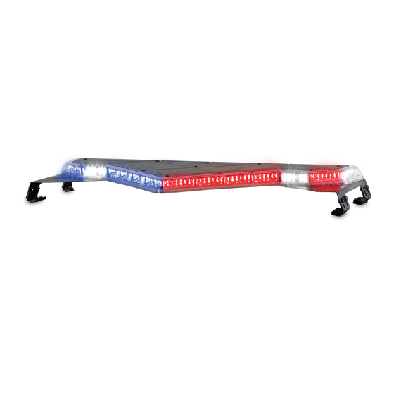
An Overview of the Valor Light Bar ® An Overview of the Valor Light Bar The Valor Light Bar is a single-level LED light bar with ROC™ (Reliable On-Board Circuitry) and Solaris ® LED technologies. ROC eliminates approximately 85 percent ™... -
Page 11: Table 1 Dimensions
An Overview of the Valor Light Bar ® Other advanced features of the Valor Light Bar include: • A high degree of reliability through the use of advanced microprocessors and other integrated circuits. • One piece seamless construction that eliminates leaking bulkhead gaskets. •... -
Page 12: Preparing The Valor For Installation
Preparing the Valor for Installation Preparing the Valor for Installation Taking the preparatory steps in this chapter before mounting and wiring the light bar to a vehicle will help ensure that your installation is fast, easy, and error free. In addition to instructions for quick testing the light bar, this chapter has instructions for changing default settings and flash patterns with the Serial Interface Module. -
Page 13: Figure 1 Serial Interface Module Connections For Programming
Preparing the Valor for Installation The numbers in the steps below refer to the wires in Figure 1. To connect the Valor to the battery and Serial Interface Module: 1. To supply power to the light bar, use a fully-charged 12-volt automotive battery with terminal lugs. -
Page 14: Selecting External Signalmaster Control
Preparing the Valor for Installation Selecting External SignalMaster Control The Interface Module comes factory-set for the INTERNAL SignalMaster option. See “Selecting Internal SignalMaster Control (Factory Default)” on page 14. With EXTERNAL control the Interface Module drives each SignalMaster head independently via an external Federal Signal SignalMaster controller or the SS2000SM Series Siren. -
Page 15: Entering Program Mode
Preparing the Valor for Installation Table 4 SW2 DIP switch settings in the Serial Interface Module Switch Setting Switch Down Number (OFF) (ON) Function Front/Rear LEDs cut off (turn off) when 12 Vdc is applied their control wires (Table 5 on page 16) Front/Rear LEDs enable (turn on) when 12 Vdc is applied to their control wires Keep in OFF position. -
Page 16: Table 5 Control Wires From The Serial Interface Module
Preparing the Valor for Installation Table 5 Control wires from the Serial Interface Module Light Bar Controls Wire Color Description Mode 1 Blue Lowest priority Mode 2 Blue/White Overrides Mode 1. Mode 3 Black/Red Overrides Modes 1 and 2. Steady Burn Red/White One or more LEDs steadily burn when 12 Vdc (HotFoot only) -
Page 17: Figure 2 Connectors And Switches On The Serial Interface Module
Preparing the Valor for Installation SW2 DIP Switch Settings in the Serial Interface Module For the location of SW2, see Figure 2. Table 4 on page 15 lists the DIP switch settings in the Serial Interface Module for programming flash patterns. Figure 2 Connectors and switches on the Serial Interface Module SW1 PUSHBUTTON FOR SELECTING FLASH PATTERNS... - Page 18 Preparing the Valor for Installation 3. Remove 12 Vdc from the Mode 3 control wire. Mode 2 1. Apply 12 Vdc (+BAT) to the Mode 2 control wire (blue/white) from the Serial Interface Module to display the assigned pattern. 2. On the Serial Interface Module, press and release the SW-1 pushbutton until the pattern you want appears on the light bar.
-
Page 19: Exiting Program Mode
Preparing the Valor for Installation 1. Unplug the 24-pin harness from the Serial Interface Module. 2. See Table 6. On the Serial Interface Module, set Switch 7 and Switch 8 on SW2 to select a method of operation. Each setting is independent of the other. 3. -
Page 20: Wiring The Valor In The Vehicle
Wiring the Valor in the Vehicle Wiring the Valor in the Vehicle Before proceeding, ensure that the light bar has been installed on the vehicle roof in accordance with the instructions included with the mounting kit. Depending on the type of vehicle and mounting system feature, there are two options available for installing the light bar to the roof of the vehicle: hook-on mounting or permanent mounting. -
Page 21: Connecting Power To The Light Bar
Wiring the Valor in the Vehicle AIRBAG DEPLOYMENT: Do not install equipment or route wiring in the deployment path of an airbag. Failure to observe this warning will reduce the effectiveness of the airbag or potentially dislodge the equipment, causing serious injury or death. -
Page 22: Installing The Serial Interface Module
Wiring the Valor in the Vehicle EXPLOSION HAZARD: To avoid a battery explosion, always disconnect the negative battery cable first and reconnect it last. Avoid causing a spark when connecting near or to the battery. The gases produced by a battery can cause a battery explosion that could result in vehicle damage and serious injury. -
Page 23: Figure 3 Relay-Isolating Devices With Large Filter Capacitors
Wiring the Valor in the Vehicle DO NOT DRILL INTO SERIAL INTERFACE MODULE: DO NOT drill holes into ANY part of the Serial Interface Module. Damage to the unit, serious injury, or death may result. DRILLING PRECAUTIONS: When drilling holes, check the area you are drilling into to ensure that you do not damage vehicle components while drilling. -
Page 24: Wiring The Serial Interface Module
Wiring the Valor in the Vehicle Wiring the Serial Interface Module FUSE ELECTRICAL SOURCES: Always fuse current/voltage sources with a fuse connected near the power source. Ensure that the fuse is properly rated to protect the electrical load, the wiring, and the connectors used in the circuit. Failure to follow this notice could result in vehicle or equipment damage. - Page 25 Wiring the Valor in the Vehicle Front Cutoff When 12 Vdc (+BAT) is applied to the Front Cutoff control wire (green/white), the selected Mode operation is deactivated to the front of the light bar. Only the rear LEDs function. Additionally, with Flash Takedown/Alley (red/black) active, only the alley lights turn on.
- Page 26 Wiring the Valor in the Vehicle Low Power NOTE: Low power mode is disabled when the light bar is in MODE 3 or displaying the Intersection flash pattern. USE THE DIMMING/LOW POWER FUNCTION PROPERLY: Enabling the Low Power function in the light bar may cause the light output to fall below certain light output standards and guidelines for emergency warning lights.
-
Page 27: Table 7 Signalmaster Control Wires And Warning Patterns
Wiring the Valor in the Vehicle independent ground signal to turn on each head (Figure 7). For the switch setting in the Serial Interface Module, see “Selecting External SignalMaster Control” on page 14. To activate the light bar’s internal SignalMaster controller, apply 12 Vdc (+BAT) to the SignalMaster control wires (Table 7 and Figure 5). -
Page 28: Figure 6 Signalmaster Control Functions Wired To 12 Vdc For Internal Sim Control
Wiring the Valor in the Vehicle Figure 6 SignalMaster control functions wired to 12 Vdc for internal Serial Interface Module control J1 CABLE TO POWER (+12 Vdc) SERIAL INTERFACE MODULE BLACK/RED MODE 3 BLUE/WHITE MODE 2 BLUE MODE 1 RED/WHITE STEADY BURN (or SCENE LIGHT, LEFT with SW-2 Switch 3 down [ON] in the Serial Interface Module) -
Page 29: Figure 7 Signalmaster Control Functions Wired To Ground For External Sim Control
Wiring the Valor in the Vehicle Figure 7 SignalMaster control functions wired to ground for external Serial Interface Module control J1 CABLE TO POWER (+12 Vdc) SERIAL INTERFACE MODULE BLACK/RED MODE 3 MODE 2 BLUE/WHITE BLUE MODE 1 STEADY BURN RED/WHITE (or SCENE LIGHT, LEFT with SW-2 Switch 3 down [ON] in the Serial Interface Module) -
Page 30: Figure 8 Typical Connections With A Signalmaster Controller (External Control)
Wiring the Valor in the Vehicle WHT/RED RED/GRN BLU/RED ORG/GRN GRN/BLK/WHT BLU (MODE 1) BLU/WHT (MODE 2) BLK/RED (MODE 3) WHT/BLK (TD) GRN/BLK (L. AL) ORG/RED (R. AL) Valor Light Bar ® Federal Signal www.fedsig.com... -
Page 31: Figure 9 Typical Connections With A Sw400Ss Switch Module (Internal Control)
Wiring the Valor in the Vehicle +12 V RED (LEFT) GRN (CENTER) GRN/BLK/WHT (RIGHT) ORG/GRN (WARN1) ORG (WARN2) WHT/RED (FAST) BLU (MODE 1) BLU/WHT (MODE 2) BLK/RED (MODE 3) WHT/BLK (TD) GRN/BLK (L. AL) ORG/RED (R. AL) Installation, Maintenance, and Service Manual Federal Signal www.fedsig.com... -
Page 32: Figure 10 Typical Connections With A Smartsiren Model Ss2000Sm Controller
Wiring the Valor in the Vehicle WHT (1) BRN (2) GRN/BLK/WHT GRN (3) ORG/GN) ORN (4) PRP (5) BLU/RED GRA (6) RED/GRN YEL (7) WHT/RED BLU (8) NONE (9) RED+ (10) BLK− (11) Valor Light Bar ® Federal Signal www.fedsig.com... -
Page 33: Figure 11 Typical Connections With A Non-Signalmaster Controller
Wiring the Valor in the Vehicle BLU (MODE 1) BLU/WHT (MODE 2) BLK/RED (MODE 3) WHT/BLK (TD) GRN/BLK (L. AL) ORG/RED (R. AL) Installation, Maintenance, and Service Manual Federal Signal www.fedsig.com... -
Page 34: Figure 12 Typical Connections With A Pa640 Controller
Wiring the Valor in the Vehicle BLK/RED (MODE 3) RED/BLK (FL TKD/AL) BLU/WHT (MODE 2) BLU (MODE 1) WHT/BLK (TD) GRN/BLK (L.AL) ORG/RED (R.AL) Valor Light Bar ® Federal Signal www.fedsig.com... -
Page 35: Maintaining And Servicing The Valor
Maintaining and Servicing the Valor Maintaining and Servicing the Valor This chapter describe how to maintain and service the Valor light bar. Establishing a regular maintenance and inspection schedule extends the life of the light bar and ensures safety. For service, support, or replacement parts, contact the Federal Signal Service Department at 1-800-433-9132, 7 a.m. -
Page 36: Removing And Reinstalling The Light Bar Lens
Maintaining and Servicing the Valor Removing and Reinstalling the Light Bar Lens The light bar lens, which is the top half of the Valor housing, covers the ROC (Reliable Onboard Circuitry) PCBs and controller PCB. Tool required: T27 Torx driver Removing the Lens To remove the lens: 1. -
Page 37: Replacing A Pcb
Maintaining and Servicing the Valor Reinstalling the Lens To reinstall the lens: 1. Reinstall the gasket and lens. To prevent cross-threading the barrel nuts, back them counterclockwise until you hear the click of the threads engaging. 2. Tighten the barrel nuts to 16-24 in-lb in the sequence shown in Figure 13 on page 36. -
Page 38: Disconnecting/Connecting Power And Cat5 At The Light Bar
Maintaining and Servicing the Valor 4. Inspect the O-rings and the lip seal for deformation, brittleness, cuts, or tears. To maintain watertightness, replace a questionable O-ring or seal. 5. Note and record the connection to the PCB (Figure 14 on page 37), then lift it and disconnect the harnesses. -
Page 39: Figure 16 Secondary Lock Mechanism In The Plug And Receptacle
Maintaining and Servicing the Valor Figure 16 Secondary lock mechanism in the plug and receptacle CPA (connector position assurance) Locking Latch Locking Ramp Receptacle Plug Disconnecting a Cable at the Light Bar To disconnect the power or CAT5 cable: 1. Pull back the CPA on the receptacle. 2. - Page 40 Maintaining and Servicing the Valor Reconnecting a Cable at the Light Bar To reconnect the power or CAT5 cable: 1. Firmly push the connectors together until you feel them snap together and you hear a click. This tactile and audible confirmation ensures that the connectors are properly and fully mated.
-
Page 41: Troubleshooting The Light Bar
Maintaining and Servicing the Valor Troubleshooting the Light Bar This section provides troubleshooting assistance for common problems. If you have any questions left unanswered, call the Federal Signal Service Department at 1-800- 433-9132, 7 a.m. to 5 p.m., Monday through Friday (CT). Table 8 Troubleshooting tips Problem Corrective Action... -
Page 42: Quick Testing The Valor With The Light Bar Test
Maintaining and Servicing the Valor Problem Corrective Action The light bar has a delayed • Ensure that the connections on the Serial Interface Module are kept response to being shut off separate from strobe supplies. • Check all the ground connections, especially on the Serial Interface Module. -
Page 43: Testing The Steady Burn Leds (Hotfoot Only)
(default setting). 2. Remove 12 Vdc from the Mode and Steady Burn control wires. Getting Technical Support and Service For technical support and service, please contact: Service Department Federal Signal Corporation Phone: 1-800-433-9132 Email: empserviceinfo@fedsig.com www.fedsig.com Getting Repair Service The Federal Signal factory provides technical assistance with any problems that cannot be handled locally. -
Page 44: Replacement Parts
Getting Technical Support and Service Replacement Parts This section contains a partial list of replacement parts. To order replacement parts, call the Federal Signal Service Department at 1-800-433-9132 or 1-708-534-3400, 7 a.m. to 5 p.m., Monday through Friday (Central Time) or contact your nearest distributor.
Need help?
Do you have a question about the Valor VALR44 and is the answer not in the manual?
Questions and answers