Advertisement
Quick Links
Advertisement

Subscribe to Our Youtube Channel
Related Manuals for Walker Edison Woodviolet BR60BRX6D-T


Summary of Contents for Walker Edison Woodviolet BR60BRX6D-T
- Page 1 Item: BR60BRX6D -T Revised 11/2023-V1...
- Page 2 , hammmer and tape measure...
- Page 3 The side drawer with WARNING LABEL, should be mounted in highest drawer. 12 pcs Top panel Drawer handle Center drawer front 02 pcs Left side panel Drawer front 04 pcs Right side panel Drawer bottom Bottom panel 06 pcs Division Drawer back 06 pcs Wood slider...
- Page 4 45 pcs Ø8*30mm Wooden dowel Ø10*20mm Wooden dowel Ø4*25mm Screw Ø3,5*30mm Screw Ø4,0*40mm Screw Nail 10*7 Screw Ø7*60mm Ø6*31mm Cam bolt Ø15*11mm Cam lock Back panel 15*15mm metal plate Hex Key Wall anchor Washer Ø4,0*14mm Screw Ø6*35mm Plastic bush...
- Page 5 Wooden dowel Ø8*40mm Threaded foot insert Threaded 01 pc Ø1/4*25mm leveling foot Screw Ø7*40mm Metal plate 75*45*2mm...
- Page 6 Attention to the Step 1 dowel length: ø10*20mm Ø10*20mm Insert wood dowel (B) into part 6 and 17. Step 2 Insert wood dowel (A) into parts 2, 3, 5, 8, 9, 10, 18, 19 and 21. Ø8*30mm...
- Page 7 Step 3 1 - Ensure cam bolt is installed straight and not at an angle. 2 - Tighten cam bolt until shoulder on cam bolt is flush. Do not over-tigh- ten. Attach cam bolt (H) into the holes in parts 1, 12, and 13 with Phillips head screwdriver.
- Page 8 Step 5 Rotate part 5. Secure parts 6 to part 5 with screw (C) and Phillips head screwdriver. Ø4*25mm Step 6 Attach parts 2 and 5 to part 1.
- Page 9 Step 7 Align the opening in cam lock to the cam bolt and press into opening. Using a screwdriver, rotate the cam lock until it engages with the cam bolt and locks in place (anywhere between 90-180 degrees). Do not over-tighten the cam lock.
- Page 10 Step 9 Attach part 3 to part 8 and to part 1. Step 10 Insert Cam lock (I) into the holes in the part 3, and attach with Phillips head screwdriver. Ø15*11mm P.10...
- Page 11 Step 11 Insert threaded foot insert (Q) into the hole in the part 10 and insert threaded leveling foot (R). Ø1/4*25mm Step 12 Ø7*60mm Attach leg 9 and 10 to part 4 with bolt (G) and hex key (K). Step 13 Ø7*40mm Attach Metal plate (T) to part 9 with bolt (S) and hex key (K).
- Page 12 Step 14 Attach leg 9 with Sheet Metal, Ø4,0*14mm to part 4 with Screws (N) and Phillips head screwdriver. Step 15 Attach part 4 to parts 2, 3 and 5 with Screws (E) and Phillips head screwdriver. Ø4,0*40mm P.12...
- Page 13 Step 16 Name and address of the supplier and date of production. 10*7 Secure back panel 7 to the dresser back with nails (F), back panel metal plate (J) and hammer. 15*15mm Step 17 FRONT Ø8*30mm Insert wood dowel (A) into the front hole in the wood sliders 6 and 17. P.13...
- Page 14 Step 18 Attach part 12 to part 11 with screws (C) Phillips head screwdriver. Attach part 13 to part 11 with screws (C) Phillips head screwdriver. Ø4*25mm Step 19 Attach part 18 and 21 to part 12. Attach part 18 and 21 to part 13. Attach part 18 and 19 to part 13.
- Page 15 Step 20 Insert Cam lock (I) into the holes in the parts 18, 19 and 21, and attach with Phillips head screwdriver. Ø15*11mm Step 21 Insert part 14 into groves and secure part 15 with screws (D) and Phillips head screwdriver. Ø3,5*30mm P.15...
-
Page 16: Warning Label
Step 22 The side drawer with WARNING LABEL, should be mounted in highest drawer. Insert wood dowel (P) on the inside of all drawers, with the drawer inside the unit after having passed the wood dowel that is in the drawer slide. dowel is not flush with the panel, it is a little inside the drawer to help when you need to remove the lock dowel to remove the drawer. - Page 17 Step 23 Wall anchor and hardware are included with this product. Please make sure hardware is suitable for your walls before types of anchors. Ø6mm Attach part (L) with screw (N) and washer (M), in the frame of top panel unit using Phillips head screwdriver. With drilling machine make one hole in the wall, insert part (O) in the hole.
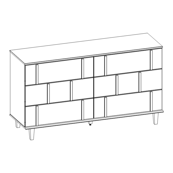
- Page 18 Assembly Complete! P.18...
Need help?
Do you have a question about the Woodviolet BR60BRX6D-T and is the answer not in the manual?
Questions and answers