
Subscribe to Our Youtube Channel
Related Manuals for Smarteh LPC-2.CH1


Summary of Contents for Smarteh LPC-2.CH1
- Page 1 USER MANUAL Longo programmable controller LPC-2.CH1 special module Version 2 SMARTEH d.o.o. / Trg tigrovcev 1 / 5220 Tolmin / Slovenia / Tel.: +386(0)5 388 44 00 / e-mail: info@smarteh.si / www.smarteh.si...
- Page 2 Longo programmable controller LPC-2.CH1 special module Written by SMARTEH d.o.o. Copyright © 2012, SMARTEH d.o.o. User Manual Document Version: 002 July 1, 2012...
- Page 3 Vibrations and climatic-mechanical: EN 60068-2-6, EN 60068-2-27, • EN 60068-2-29 Smarteh d.o.o. operates a policy of continuous development. Therefore we reserve the right to make changes and improvements to any of the products described in this manual without any prior notice.
-
Page 4: Table Of Contents
Longo programmable controller LPC-2.CH1 special module Longo programmable controller LPC-2.CH1 special module 1 DESCRIPTION...................1 2 FEATURES..................2 3 OPERATION..................3 3.1 Parameters................3 4 INSTALLATION..................4 4.1 Connection scheme..............4 4.2 Mounting frame selection............6 4.3 Mounting instructions..............7 4.4 Module labeling................9 5 TECHNICAL SPECIFICATIONS..............10 6 CHANGES ..................11... -
Page 5: Description
Longo programmable controller LPC-2.CH1 special module 1 DESCRIPTION LPC-2.CH1 RFID reader is intended to be used as presence registering device and key-card holder. Module also provides touch buttons (TB) for activating requested messages. This messages are convenient to notify personnel (e.g. occupied, do not disturb). -
Page 6: Features
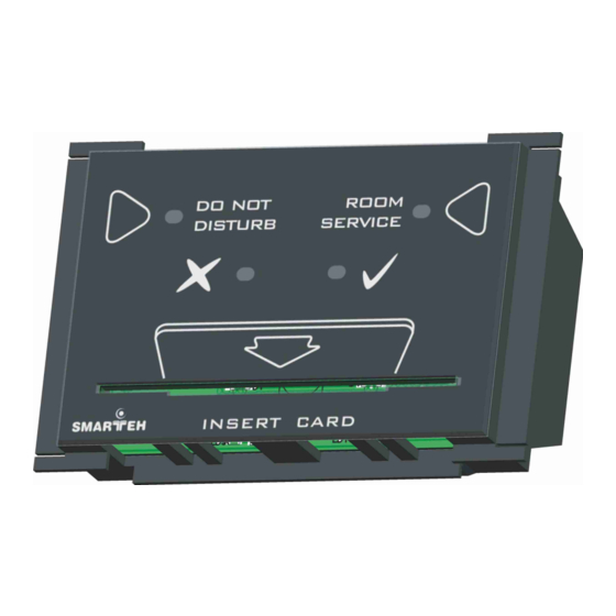
Longo programmable controller LPC-2.CH1 special module 2 FEATURES Figure 1: LPC-2.CH1 special module Table 1: Technical data RFID reader RFID card slot Adjustable LED intensity LEDs for showing activated messages & requests: do not disturb, room service 2 touch buttons for activating messages & requests: do not disturb, room service OK “... -
Page 7: Operation
Longo programmable controller LPC-2.CH1 special module 3 OPERATION Operation of the CH1 module is also dependent on parameters received on RS485 communication channel. If RFID card is inserted into slot, reader tries to resolve RFID tag code. If code is read successfully, module activates status iIDNew and sends RFID code in iIDW1-iIDW3 status fields. -
Page 8: Installation
Longo programmable controller LPC-2.CH1 special module 4 INSTALLATION 4.1 Connection scheme Figure 2: Connection scheme... - Page 9 Longo programmable controller LPC-2.CH1 special module Table 2: K1 K1.1 Ground K1.2 10 – 24 VDC Power supply input K1.3 RS485 A Data receive/send line A K1.4 RS485 B Data receive/send line B Table 3: LEDs & Buttons On: request active...
-
Page 10: Mounting Frame Selection
Master ● Frames of other vendors most probably suits as well, but they were not verified by Smarteh. Before installation verify compatibility of non listed frames. Module housing has a fin on each side, which can be easily removed with knife cutter or pliers. This adaptation enables housing to be build in various frame formats with two different depths. -
Page 11: Mounting Instructions
Longo programmable controller LPC-2.CH1 special module 4.3 Mounting instructions Figure 4: Housing dimensions Dimensions in millimeters. • All connections, module attachments and assembling must be done while module is not connected to the main power supply. Module should not be mounted outdoors. - Page 12 Longo programmable controller LPC-2.CH1 special module 1. Set the correct RS485 address (S1 switch) for LPC-2.CH1 (refer to the Table 4). 2. Connect interconnection cable to the connector K1. Max. allowed tractive force is 30 N. 3. Put the LPC-2.CH1 in mounting frames 4.
-
Page 13: Module Labeling
S/N: CH1-S9-1000000003 is the serial number. • CH1 – short product name, • S9 – user code (test procedure, e.g. Smarteh person xxx), • 10 – year (last two cyphers) • 00000003 – current stack number; previous module would have the stack number •... -
Page 14: Technical Specifications
Longo programmable controller LPC-2.CH1 special module 5 TECHNICAL SPECIFICATIONS Table 6: Technical specifications Power supply from MCU Interconnection connector type RJ12 6/6 Power consumption RFID type EM4100, 125kHz, Manchester 64, read only Max. reading distance RFID card inserted into CH1 slot... -
Page 15: Changes
Longo programmable controller LPC-2.CH1 special module 6 CHANGES The following table describes all the changes to the document. Date Description 1.1.2012 CGP General update 1.10.2010 The initial version, issued as LPC-2.CH1 module UserManual. -
Page 16: Notes
Longo programmable controller LPC-2.CH1 special module 7 NOTES...
Need help?
Do you have a question about the LPC-2.CH1 and is the answer not in the manual?
Questions and answers