Table of Contents
Advertisement
Quick Links
Information contained herein is classified as EAR99 under the U.S.
Export Administration Regulations. Export, reexport or diversion
contrary to U.S. law is prohibited.
OPERATING INSTRUCTIONS FOR
MODEL 3000RS-P
Percent Oxygen Analyzer
Toxic gases and or flammable liquids may be present in this monitoring
system.
Personal protective equipment may be required when servicing this
instrument.
Hazardous voltages exist on certain components internally which may persist
for a time even after the power is turned off and disconnected.
Only authorized personnel should conduct maintenance and/or servicing.
Before conducting any maintenance or servicing, consult with authorized
supervisor/manager.
Use and Disclosure of Data
DANGER
P/N M95585
12/12/23
Advertisement
Table of Contents

Related Manuals for Teledyne TEXIO PTE6-200


Summary of Contents for Teledyne TEXIO PTE6-200
- Page 1 Use and Disclosure of Data Information contained herein is classified as EAR99 under the U.S. Export Administration Regulations. Export, reexport or diversion contrary to U.S. law is prohibited. OPERATING INSTRUCTIONS FOR MODEL 3000RS-P Percent Oxygen Analyzer P/N M95585 12/12/23 DANGER Toxic gases and or flammable liquids may be present in this monitoring system.
- Page 3 Teledyne or an authorized service center. We assume no liability for direct or indirect damages of any kind and the purchaser by the acceptance of the equipment will assume all liability for any damage which may result from its use or misuse.
- Page 4 3000RS-P series analyzers installed in a custom 19" chassis and ready to mount in a standard instrument rack. Sensor Options Available for the Instrument with the Above Serial Number: ❑ ❑ ❑ ❑ _________ Teledyne Analytical Instruments...
- Page 5 STAND-BY: Instrument is on Stand-by, but circuit is active. GROUND: Protective Earth CAUTION: The operator needs to refer to the manual for further information. Failure to do so may compromise the safe operation of the equipment. CAUTION: Risk of Electrical Shock Teledyne Analytical Instruments...
-
Page 6: Safety Messages
Technician Symbol: All operations marked with this symbol are to be performed by qualified maintenance personnel only. NOTE: Additional information and comments regarding a specific component or procedure are highlighted in the form Symbol of a note. Teledyne Analytical Instruments... - Page 7 Manuals do get lost. Additional manuals can be obtained from Teledyne at the address given in the Appendix. Some of our manuals are available in electronic form via the internet. Please visit our website at: www.teledyne-ai.com.
- Page 8 Since the use of this instrument is beyond the control of Teledyne, no responsibility by Teledyne, its affiliates, and agents for damage or injury from misuse or neglect of this equipment is implied or assumed.
-
Page 9: Table Of Contents
2.4 Electronics and Signal Processing Installation ................... 19 3.1 Unpacking the Analyzer 3.2 Mounting the Analyzer 3.3 Rear Panel Connections 3.3.1 Gas Connections 3.3.2 Electrical Connections 3.3.2.1 24VDC Input Power 3.3.2.2 50-Pin Equipment Interface Connector 3.3.2.3 RS-232 Port Teledyne Analytical Instruments viii... - Page 10 4.5.8.3 Profibus Task 4.5.9 Analog Output 4.5.9.1 Range Identification 4.5.9.2 Concentration 4.5.10 More Screen 4.5.10.1 Serial Number 4.5.10.2 Negative Number 4.5.10.3 Stream Selection 4.5.10.4 Model Number 4.5.11 Version 4.5.12 System Status 4.5.13 Firmware Upgrade 4.6 The Range Function Teledyne Analytical Instruments...
- Page 11 5.2.4 Installing a New Micro-Fuel Cell 5.3 Fuse Replacement 5.4 System Self Diagnostic Test 5.5 Major Internal Components 5.6 Cleaning 5.7 Troubleshooting Appendix ..................114 A-1 Model 3000RS-P Specifications A-2 Recommended 2-Year Spare Parts List A-3 Drawing List Teledyne Analytical Instruments...
- Page 12 Percent Oxygen Analyzer A.4 Application notes A-5 Material Safety Data Sheet Teledyne Analytical Instruments...
- Page 13 Figure 3-4: Remote Probe Connections ........29 Figure 3-5: FET Series Resistance ..........29 Figure 4-1: Analyze Screen Display ..........37 Figure 5-1: Cell Holder ..............109 Figure 5-2: Removing the Micro-Fuel Cell ........109 Figure 5-3: Rear Panel Removal ..........112 Teledyne Analytical Instruments...
- Page 14 Table 3-2: Alarm Relay Contact Pins ..........26 Table 3-3: Remote Calibration Connections ........27 Table 3-4: Range ID Relay Connections ........28 Table 3-5: Commands via RS-232 Input ........30 Table 5-1: Self Test Failure Codes ..........111 Teledyne Analytical Instruments xiii...
-
Page 16: Introduction
Introduction Introduction 1.1 Overview The Teledyne Analytical Instruments Model 3000RS-P is a redesigned compact version of the touchscreen model 3000PA Percent Oxygen Analyzer. It is a versatile microprocessor-based instrument for detecting oxygen at percent level in a variety of gases. This manual covers the Model 3000RS-P general purpose flush-panel rack-mount units only. -
Page 17: Model Designations
1.4 Model Designations 3000RS-P: Standard model. 3000RS-P-C: In addition to all standard features, this model also has separate ports for zero and span gases, and built-in control valves. The internal valves are entirely under the control of the 3000RS-P Teledyne Analytical Instruments... -
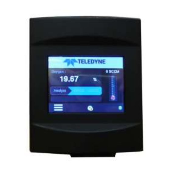
Page 18: Front Panel (Operator Interface)
Figure 1-1: Model 3000RS-P Front Panel • Concentration Display: When in Analysis mode, the display region indicates a continuous readout from 0 % though 25%. It is accurate across all analysis ranges without the discontinuity inherent in analog range switching. Teledyne Analytical Instruments... - Page 19 Shows the sample flow values on a simulated flowmeter from 0 to 100%. • Alarm Indicator: Indicates whether an alarm is triggered Alarm 1 Alarm 2 • Communication Status: LAN status icon displays when the LAN connection established. Teledyne Analytical Instruments...
-
Page 20: Front Access Door
1.7 Rear Panel (Equipment Interface) The rear panel, shown in Figure 1-2, contains the gas and electrical connectors for external inlets and outlets. The connectors are described briefly here and in detail in the Installation chapter of this manual. Teledyne Analytical Instruments... -
Page 21: Figure 1-2: Model 3000Rs-P Rear Panel
• Analog Outputs: 0–1 VDC concentration plus 0-1 VDC range ID, and isolated 4–20 mA DC plus 4-20 mA DC range • Alarm Connections: 2 concentration alarms and 1 system alarm. • Remote Span/Zero Digital inputs allow external control of analyzer calibration. Teledyne Analytical Instruments... - Page 22 Note: If you require highly accurate Auto Cal timing, use external Auto Cal control where possible. The internal clock in the Model 3000RS-P is accurate to 2-3 %. Accordingly, internally scheduled calibrations can vary 2-3 % per day. Teledyne Analytical Instruments...
-
Page 23: Operational Theory
Micro-Fuel Cell: In the battery, all reactants are stored within the cell, whereas in the Micro-Fuel Cell, one of the reactants (oxygen) comes from outside the device as a constituent of the sample gas being analyzed. The Micro-Fuel Cell is therefore a hybrid Teledyne Analytical Instruments... -
Page 24: Anatomy Of A Micro-Fuel Cell
The other end of the cell is a contact plate consisting of two concentric foil rings. The rings mate with spring-loaded contacts in the sensor block assembly and provide the electrical connection to the rest of the analyzer. Figure 2-2 illustrates the external features. Teledyne Analytical Instruments... -
Page 25: Figure 2-2: Micro-Fuel Cell
At the rear of the cell, just below the anode structure, is a flexible membrane designed to accommodate the internal volume changes that occur throughout the life of the cell. This flexibility assures that the sensing membrane remains in its proper position, keeping the electrical output constant. Teledyne Analytical Instruments... -
Page 26: Electrochemical Reactions
The overall reaction for the fuel cell is the SUM of the half reactions above, or: →2PbO 2Pb + O (These reactions will hold as long as no gaseous components capable of oxidizing lead—such as iodine, bromine, chlorine and fluorine—are present in the sample.) Teledyne Analytical Instruments... -
Page 27: The Effect Of Pressure
(within ± 1 % oxygen). In practical application, zeroing may be used to compensate for the combined zero offsets of the cell and the electronics. (The electronics is zeroed automatically when the instrument power is turned on.) Teledyne Analytical Instruments... -
Page 28: Sample System
For metric system installations, 6 mm adapters are available for instruments to be used if required. The sample or calibration gas flows through a digital flow sensor which reports the flow downstream from the cell. Figure 2-5 shows the internal piping layout for the standard model. Teledyne Analytical Instruments... -
Page 29: Figure 2-5: Piping Layout And Flow Diagram For Standard Model
Sample In port by teeing to the port with appropriate valves. The shaded portion of the diagram shows the components added when the –C option is ordered. The valving is installed inside the 3000RS-P-C enclosure and is regulated by the instrument’s internal electronics. Figure 2-6: Flow Diagram Teledyne Analytical Instruments... -
Page 30: Electronics And Signal Processing
REAR PANEL PCB CELL HOLDER MAIN PCB MID PLANE PCB AUTO CAL VALVES Figure 2-7: 3000RS-P Internal Electronic Component Location The second stage amplifier also supplies temperature compensation for the oxygen sensor output. This amplifier circuit incorporates a ther- Teledyne Analytical Instruments... - Page 31 4-20 mA DC and the 0-1 VDC analog concentration signal outputs, and the analog range ID outputs. Signals from the power supply are also monitored, and through the microprocessor, the system failure alarm is activated if a malfunction is detected. Teledyne Analytical Instruments...
-
Page 32: Figure 2-8: Block Diagram Of The Model 3000Rs-P Electronics
Percent Oxygen Analyzer Operational Theory Figure 2-8: Block Diagram of the Model 3000RS-P Electronics Teledyne Analytical Instruments... -
Page 34: Unpacking The Analyzer
RS analyzers. There is also a single cover option that includes the cover and feet for bench top use of a single RS analyzer. The touch screen operator control buttons are mounted on the front panel, which is hinged at the bottom and provides access to the sensor Teledyne Analytical Instruments... -
Page 35: Rear Panel Connections
Figure 3-2 shows the Model 3000RS-P rear panel. There are ports for gas, power, and equipment interface. The Zero in and Span in ports are not included on the standard model but are available as options (Auto Cal option). Teledyne Analytical Instruments... -
Page 36: Gas Connections
The restrictor for low pressure (for pressure less than 5 psig) or for high pressure applications (5-50psig) should set Teledyne Analytical Instruments... - Page 37 EXHAUST OUT: Exhaust connections must be consistent with the hazard level of the constituent gases. Check Local, State, and Federal laws, and ensure that the exhaust stream vents to an appropriately controlled area if required. Teledyne Analytical Instruments...
-
Page 38: Electrical Connections
3000RS series instrument as 24 vdc power is distributed. Fuse recommendation is 0.5 A 250 V Type T, slow blow. CAUTION: POWER IS APPLIED TO THE INSTRUMENT'S CIRCUITRY AS LONG AS THE INSTRUMENT IS CONNECTED TO THE POWER SOURCE. Teledyne Analytical Instruments... -
Page 39: 50-Pin Equipment Interface Connector
20 mA at full scale %. (Full scale = 100% of programmable range.) 4–20 mA DC Range ID: 8 mA = Low Range, 12 mA = Medium Range, 16 mA = High Range, 20 mA = Air Cal Range. Teledyne Analytical Instruments... -
Page 40: Table 3-1: Analog Output Connections Pin Function
• Can be configured as high (actuates when concentration is above threshold), or low (actuates when concentration is below threshold). • Can be configured as failsafe or non-failsafe. • Can be configured as latching or non-latching. • Can be configured out (defeated). Teledyne Analytical Instruments... -
Page 41: Table 3-2: Alarm Relay Contact Pins
Floating input. 5 to 24 V input across the + and – pins put the Span: analyzer into the Span mode. Either side may be grounded at the source of the signal. 0 to 1 volt across the terminals allows Span mode to terminate when done. A synchronous signal must open Teledyne Analytical Instruments... -
Page 42: Table 3-3: Remote Calibration Connections
3. When CRC opens again, send a span command until the CRC closes. (The CRC will quickly close.) 4. When the CRC closes, remove the span command. When CRC opens again, zero and span are done, and the sample is being analyzed. Teledyne Analytical Instruments... -
Page 43: Table 3-4: Range Id Relay Connections
Pins 13 (+) and 29 (–). Remote Valve Connections: The 3000RS-P is a single-chassis instrument, which has no Remote Valve Unit. Instead, the Remote Valve connections are used as a method for directly controlling external sample/zero/span gas valves. See Figure 3-4. Teledyne Analytical Instruments... -
Page 44: Figure 3-4: Remote Probe Connections
In addition, each individual line has a series FET with a nominal ON resistance of 5 ohms (9 ohms worst case). This can limit the obtainable voltage, depending on the load impedance applied. See Figure 3-5. Figure 3-5: FET Series Resistance Teledyne Analytical Instruments... -
Page 45: Port
Table 3-6 lists certain RS-232 values that are required by the 3000RS-P implementation. Table 3-6: Required RS-232 Options Parameter Setting Baud 9600 Byte 8 bits Parity none Stop Bits Message Interval 2 seconds. When CRC opens again, zero and span are done, Teledyne Analytical Instruments... -
Page 46: Profibus Port
(see section 3.3.1). • Check that inlet sample pressure is within the accepted range (see section 3.3.1). • Power up the system and test it by repeating the Self- Diagnostic Test as described in Chapter 4, Section 4.3.5. Teledyne Analytical Instruments... -
Page 48: Operation
The return signal is analyzed, and at the end of the test the status of each function is displayed on the screen, either as OK or as a number between 1 and 3. (See System Self Diagnostic Test in Chapter 5, Section 5.4 for number code). Teledyne Analytical Instruments... -
Page 49: Diagnostic Screen
It will update the status [PASS/FAIL] on this screen as it proceeds. The Self-Test routine includes the following processes. - Power supply section testing, - Analog output section testing - Pre-amp testing Teledyne Analytical Instruments... - Page 50 Use the scroll bar to view the additional test results. Screen 1: Using the scroll bar, you can view all the test results. Screen 2: It is possible to skip the self-test at any time by pressing Skip button. Teledyne Analytical Instruments...
-
Page 51: Factory Reset Screen
The Electronics Offset calculation screen will display as follows: The Skip button at the bottom is used to skip the electronics test and proceed to the self-test. If the electronics offset is only partially Teledyne Analytical Instruments... -
Page 52: Main Screen
The bar at the bottom of the screen includes a menu select button, an alarm indicator, and an icon indicating current communication status. This bar will change in appearance depending on the selected function or system notification. Teledyne Analytical Instruments... - Page 53 2. Menu Icon: click on to navigate to the Menu Screen from the main screen. Status icons: 1. LAN status Icon: displays when the LAN connection established. 2. Profibus Status Icon: Displays when the Profibus is connected. Teledyne Analytical Instruments...
-
Page 54: Menu Screen
This screen has the “Back” arrow icon to navigate back to the Main screen. The Menu screen has 6 selection buttons which are, 1. Analyze - Change system to Analyze mode. 2. Span - Start Span calibration. Teledyne Analytical Instruments... -
Page 55: System Screen
Use the scroll bar on the right to view the various system functions. The System screen provides the following functions: 1. Screen 1: Password, Logout, Track/hold, Auto Cal 2. Screen 2: Self-test, Flow limit, VB Baud rate, Profibus Teledyne Analytical Instruments... -
Page 56: Password
The display screen text that accompanies each operation is reproduced, at the appropriate point in the procedure. 4.5.1 Password The Password setup function is available from the first System screen. Selecting the password option from the first System screen produces the following display: Teledyne Analytical Instruments... - Page 57 Change: This option can be used to change the existing password of the instrument. When the user presses the change option, the screen will change to Enter Password screen. Here the user has to verify the existing password to get access to change the password. Teledyne Analytical Instruments...
- Page 58 Pressing any of the above icons will display the type and format of the characters available: Qwerty pad: Lower case letters (select if another format button is currently enacted): Qwerty pad: Upper case letters: (Select if another format button is currently enacted): Teledyne Analytical Instruments...
-
Page 59: Logout
The Logout function provides a convenient means of leaving the analyzer in a password protected mode without having to shut the instrument off. By entering Logout, you effectively log off the instrument leaving the system protected against use until the password is Teledyne Analytical Instruments... -
Page 60: Track/Hold Screen
But, when HOLD is selected, the concentration alarms will remain frozen for the time displayed in the second line of the TRAK/HLD menu after the analyzer returns to the Analyze mode. The factory default is three minutes, but the delay time is program- mable. Teledyne Analytical Instruments... - Page 61 The Track/Hold screen has Output and Alarm delay settings. The Output Settings can be toggled between “Track” and “Hold” by touching the entry box. The Alarm Delay is an Edit box with a numerical pad for entering the Alarm Delay. Teledyne Analytical Instruments...
- Page 62 System screen. If any changes have been made, a message box will appear asking: “Do you want to save the changes?”. Answer with Yes or No buttons to dismiss the screen. Teledyne Analytical Instruments...
-
Page 63: Auto Cal Screen
The Zero and Span rows have Days and Hours Edit boxes. Clicking on the edit box will bring up individual number pads for entering or editing the Days and Hours setting. Teledyne Analytical Instruments... - Page 64 Edit box. Clicking on the ENT button will store the entered values and move back to the parent (Auto Cal) screen. Clicking on the back arrow will move to the Auto Cal screen as well but without saving the edited values. Teledyne Analytical Instruments...
- Page 65 (Auto Cal) screen. Clicking on the back arrow will move to the Auto Cal screen as well but without saving the edited values. Auto Cal screen has Reset, Save and Back buttons. Teledyne Analytical Instruments...
- Page 66 A. If both Zero and Span calibration have been set “ON” and SAVE is pressed, the following pop-up message will appear: B. If only the Zero calibration has been set to “ON” and the SAVE button is pressed, then the following pop-up message will appear: Teledyne Analytical Instruments...
- Page 67 System screen. If any changes have been made, then a message box will be shown asking: “Do you want to Save the changes”. Use the Yes or No buttons to answer and dismiss the screen. Teledyne Analytical Instruments...
-
Page 68: Self Test
In addition, this routine can be summoned at any time using the Self-Test function. This function is found on the second System screen. Use the scroll bar on the System screen to move to the second screen. Teledyne Analytical Instruments... -
Page 69: Flow Limit
Setting the value to zero will allow calibration regardless of flow value. The Flow Limit function is available from the second System screen. To enter this function, press System and scroll to the second screen. Teledyne Analytical Instruments... - Page 70 1. Option to enter or edit the Low Flow limit. This is an editable field. 2. Current Flow Status, Flow Fault status, and Flow rate. These three parameters are non-editable. Clicking on the Low Flow Limit Edit box will bring up a number pad for editing the displayed value. Teledyne Analytical Instruments...
- Page 71 4. Clicking on the back button will move the display back to the System screen. If any changes have been entered, a message box will appear requesting: “Do you want to Save the changes?” Use the Yes or No buttons to reply. Teledyne Analytical Instruments...
-
Page 72: Vb Baud Rate Screen
The VB Baud Rate screen allows the user to set or edit the Baud rate, Data bits, Parity type and includes dropdown selectable options. The VB Baud Rate function is available from the second System screen. To enter this function, press System and scroll to the second screen. Teledyne Analytical Instruments... - Page 73 VB Baud Rate setup screen: The Baud Rate Baud display box includes a drop-down selection of the available rates. Use the scroll bar to view all entries. Select either 2400, 4800, 9600, 19200, 38400, or 115200 bits per second. Teledyne Analytical Instruments...
- Page 74 Operation Similarly with the Data Bits entry box, the drop-down menu shows the available selections. Select either 7, 8 or 9 data bits. From the Parity entry box, the user can select None, Even or Odd parity. Teledyne Analytical Instruments...
-
Page 75: Profibus Screen
4.5.8 Profibus Screen When using Profibus communication, the Profibus function available from System screen 2 displays the Profibus configuration. System screen 2: 4.5.8.1 P ROFIBUS DDRESS Press Profibus to display the Profibus configuration screen. Teledyne Analytical Instruments... - Page 76 1. The Profibus address can range from 1 to 125. 2. Click on the “DEL” button to delete the one character at a time from the Edit box. Teledyne Analytical Instruments...
-
Page 77: Profibus Status
The Status box will indicate: • “Connected” if the 3000RS-P board is connected to the external PC software Profipercent. • “No Connection” if the 3000RS-P board profibus communication has failed to communicate the external with PC software Profipercent. Teledyne Analytical Instruments... -
Page 78: Profibus Task
Model No (LSB) - 0x08 Model Number System model no 0x09-0x0E (0x08-0x0F) will be updated Model No (MSB) - 0x0F 0x0F 0x10 Serial No (LSB) - 0x10 System serial no Serial Number (0x10 - 0x17) will be updated 0x11 - 0x16 Teledyne Analytical Instruments... - Page 79 Span Mode, Zero 0th and 1st bit. Mode System Mode The mode values Reserved 0x1C (0x1C) will be Reserved 00 - Init (0) Reserved 01 - Analyzer Reserved mode (1) 10- Span mode Reserved Teledyne Analytical Instruments...
- Page 80 System Status - Reserved 0x1F Reserved Reserved (0x1F) System will 0x20 Flow rate (LSB) Current Flow Rate update current (0x20 - 0x21) 0x21 Flow rate (MSB) flow rate. 0x22 Reserved Reserved Reserved (0x022 - 0x23) 0x23 Reserved Reserved Teledyne Analytical Instruments...
-
Page 81: Analog Output
0-1 VDC or 4-20 mA. Note that both outputs are not available at the same time. The Analog Output function is available from the third System screen. To enter this function, press System and scroll to the third System screen. System screen 3: Teledyne Analytical Instruments... - Page 82 If 4-20 ma output is chosen, there is a choice to calibrate the 4-20 ma analog outputs endpoints. The calibration buttons will appear. A DVM set in milliampere measurement will need to be connected on the corresponding 4-20 ma output pins of the D-Sub 50 pin connector Teledyne Analytical Instruments...
- Page 83 To adjust the 4-20 ma, press the button with count button and adjust the count value with the numeric keypad to change the 4 ma setting. Press the ENT button for the new adjustment to take effect and check the DVM. Teledyne Analytical Instruments...
-
Page 84: Range Identification
For example, if the analyzer is set on range that was defined as 0–100 % O , then the output would be: Voltage Signal Current Signal Output (VDC) Output (mA dc) 10.4 12.0 13.6 15.2 16.8 Teledyne Analytical Instruments... - Page 85 “Do you want to Save the changes?” Use the Yes or No buttons to reply. • “Yes” will save user entered values and move to the System screen. • “No” will discard the changes and move to System screen. Teledyne Analytical Instruments...
-
Page 86: More Screen
Serial Number, Negative Number, Stream Selection and Model Number. It is available from the third System function. System screen 3: Press More to view the additional functions. More screen: The More screen has Reset, Save, and Back buttons. Teledyne Analytical Instruments... -
Page 87: Serial Number
• “No” will discard the changes and move to System screen. 4.5.10.1 S ERIAL UMBER Serial Number is an Edit box used to enter a serial number range from 100000 to 999999. This is used in conjunction with a Teledyne Valve Box for remote valve actuation. Teledyne Analytical Instruments... -
Page 88: Negative Number
This preference is stored in non-volatile memory, so this configuration is remembered after a power shutdown. If the instrument is cold started, it will go back to default (not showing negative oxygen readings). Teledyne Analytical Instruments... -
Page 89: Stream Selection
For percent analysis the system must be equipped with an appropriate percent analysis micro fuel cell. 4.5.11 Version The Version screen is a read-only screen that displays the manufacturer, model, and software version information. It is accessible from the third System screen. System screen 3: Teledyne Analytical Instruments... -
Page 90: System Status
E. Alarm relay status and solenoid valve status F. Remote zero/span status G. Analog output status (Range ID and concentration analog outputs) Note: The System Status function is not implemented in this version. Teledyne Analytical Instruments... -
Page 91: Firmware Upgrade
C. This function will also provide an option to update the front panel UI firmware as well. D. The Firmware Upgrade function will display the firmware update date and time for both the front panel and motherboard. Teledyne Analytical Instruments... -
Page 92: The Range Function
However, the digital readout and the RS-232 output of the concentration are unaffected by the fixed range. They continue to read accurately with full precision. See Front Panel description in Chapter 1. The automatic air calibration range is always 0-25 % and is not pro- grammable. Teledyne Analytical Instruments... -
Page 93: Setting The Analog Output Ranges
This screen includes options to edit the LOW, MEDIUM, and HIGH ranges (in %) as well as the Range Type (fixed range or auto range). All ranges begin at 0 %. Note: The ranges must be increasing from low to high, for Teledyne Analytical Instruments... - Page 94 The Range screen has Reset, Save, and Back buttons. 1. Clicking on the Reset button will revert back to the old values and any changes that have been made will not be saved. 2. Clicking on the Save button will save the newly entered values. Teledyne Analytical Instruments...
-
Page 95: Fixed Range Analysis
1 VDC (or 20 mA). However, the digital readout and the RS- 232 output continue to read the true value of the oxygen concentration regardless of the analog output range. Teledyne Analytical Instruments... -
Page 96: Alarm Function
Decide whether you want the alarms to be set as: • Both high (high and high-high) alarms, or • One high and one low alarm, or • Both low (low and low-low) alarms. Teledyne Analytical Instruments... - Page 97 Follow the instructions in section 4.3.3 to enter your password. Once you have clearance to proceed, enter the Alarm function. Press the Alarm button on the Menu screen to enter the Alarm function. Menu screen: Teledyne Analytical Instruments...
- Page 98 Value of the alarm setpoint, AL–1 ### % (oxygen) • Out-of-range direction, HI or LO • Defeated? Dft–Y/N (Yes/No) • Failsafe? Fs–Y/N (Yes/No) • Latching? Ltch–Y/N (Yes/No). Use the scroll bar to view the last two items. Teledyne Analytical Instruments...
-
Page 99: Alarm Setpoint
4.7.1 Alarm Setpoint To define the alarm setpoint, touch the ALARM 1 or ALARM 2 Threshold edit box to bring up a numerical keypad. Alarm 1 Threshold set: Note: Alarm 1 is shown, Alarm 2 is identical. Teledyne Analytical Instruments... -
Page 100: Hi/Low Alarm
This mode requires an alarm to be recognized before it can be reset. 2. OFF - The alarm status will terminate when process conditions revert to non-alarm conditions. Teledyne Analytical Instruments... -
Page 101: Alarm Status
1. When alarm is active (alarm triggered), it will show “Reset Alarm 1” or “Reset Alarm 2”. If the alarm is inactive, it will not show the Reset Alarm touch button. 2. Reset: Touch the Alarm Indicator icon on the Main screen to reset the active alarm. Teledyne Analytical Instruments... -
Page 102: The Zero And Span Functions
40 psig or less when turning it back on. Readjust the gas pressure into the analyzer until the flowrate (as read on the Main screen settles between 150 and 2400 SLPM (ap- proximately 0.2 - 5 SCFH). Teledyne Analytical Instruments... -
Page 103: Zero Cal
Make sure the zero gas is connected to the instrument. Make sure the Zero calibration gas source is connected to the instrument (see Section 3.3.1). Press the Zero button on the Menu screen to enter the Zero Calibration function. Menu screen: Teledyne Analytical Instruments... -
Page 104: Auto Mode Zeroing
Details about manual and auto calibration run screens are detailed below. 4.8.1.1 A EROING When the Zero calibration mode is set to Auto and the “Touch to Start the Calibration” button is pressed, the Zero Auto Run screen is displayed. Teledyne Analytical Instruments... - Page 105 1. Message 1: “Calibration Progress” - This message displays in the Status bar as the calibration begins. 2. Message 2: A calibration countdown displays as: “Calibration 5 Left”, “Calibration 4 Left” etc. and is based on the currently calculated gain offset. Teledyne Analytical Instruments...
- Page 106 DURING A CALIBRATION will bring up a display which will allow the abort the calibration without saving. Use the Yes or No buttons to reply. • “Yes” will ABORT the calibration and move back to the Menu screen. • “No” will continue the calibration. Teledyne Analytical Instruments...
-
Page 107: Manual Mode Zeroing
ANUAL EROING When the Zero calibration mode is set to MAN and the “Touch to Start the Calibration” button is pressed, the Zero Run screen is displayed. Zero Cal screen 1: Zero Cal Manual Mode Run screen: Teledyne Analytical Instruments... - Page 108 The Zero Calibration Run screen has a Back arrow that when pressed DURING A CALIBRATION will bring up a display which will allow the abort the calibration without saving. Use the Yes or No buttons to reply. Teledyne Analytical Instruments...
- Page 109 After the calibration has FINISHED, pressing the Back arrow will bring up a similar requester. • “Yes” will save the calibration values and return to the System screen. • “No” will discard the changes and move to System screen. Teledyne Analytical Instruments...
-
Page 110: Span Cal
Five minutes is the default, but it could be adjusted anywhere from 1 to 60 minutes by user. This screen is also used to enter the span concentration of the calibration gas. Teledyne Analytical Instruments... - Page 111 To set the calibration hold time in minutes, touch the corresponding edit box to bring up the numerical pad. Enter the hold time using the keypad. Select hold time in the 10 to 15 minutes range is recommended. Teledyne Analytical Instruments...
- Page 112 ENT to save the value or the back arrow to discard the entry and dismiss the numerical pad. Start the Calibration: To begin the Span calibration, touch the corresponding box on the Span Cal screen. Teledyne Analytical Instruments...
- Page 113 5. Flow meter with flowrate and status The Calibration in Progress icon will appear only in the Auto calibration mode. It means that a calibration is in progress. When the calibration is finished or if an error occurs, the icon will stop refreshing. Teledyne Analytical Instruments...
- Page 114 The Span Calibration Run screen has a Back arrow button that when pressed DURING A CALIBRATION will bring up a display which will allow the abort the calibration without saving. Use the Yes or No buttons to reply. Teledyne Analytical Instruments...
-
Page 115: Span Manual Mode Run Screen
• “No” will discard the changes and move to System screen. 4.8.2.2 S ANUAL CREEN When the Span calibration mode is set to MAN and the “Touch to Start the Calibration” button is pressed, the Span Run screen is displayed. Teledyne Analytical Instruments... - Page 116 Slope on the screen. It takes several seconds for the first Slope value to display. Slope indicates rate of change of the Span reading. It is a sensitive indicator of stability. Once span settling completes, the information is stored in the microprocessor. Teledyne Analytical Instruments...
- Page 117 After the calibration has FINISHED, pressing the Back arrow will bring up a similar requester. • “Yes” will save the calibration values and return to the System screen. • “No” will discard the changes and move to System screen. Teledyne Analytical Instruments...
-
Page 118: Maintenance Schedule
To set the maintenance reminder, the operator must set the time and start the counter by setting up the “Maint Schedule” function in the system menu. Teledyne Analytical Instruments... - Page 119 Days Remaining shows the number of days remaining in the counter before the warning is triggered. The Reset button can be used to reset the counter back to the value of interval of days. Teledyne Analytical Instruments...
-
Page 120: No Sensor Detection Feature, Sensor Fail
If output rises above the electronic zero detection window, during the countdown, the counter is reset back to 30 minutes. To set the feature the operator must find the “Sensor Fail” function in the system menu. Teledyne Analytical Instruments... - Page 121 This is rare but it can happen. There is no recourse if this is happening other than to disable the feature as long as sensor installation has been verified. Teledyne Analytical Instruments...
-
Page 122: Routine Maintenance
The spare cell should be carefully stored in an area that is not subject to large variations in ambient temperature (75°F nominal, 24°C) or to rough handling. WARNING: The sensor used in the model 3000RS-P Percent Oxygen Analyzer uses electrolytes which contain toxic substances, mainly Lead and potassium Teledyne Analytical Instruments... -
Page 123: When To Replace A Cell
The door is held in place by a magnetic latch. 3. Lift the latch of the cell holder see Figure 5-1. 4. The cell holder and the sensor will drop. See Figure 5-2. Depending on sensor used, cell adaptor might not be in. Teledyne Analytical Instruments... -
Page 124: Figure 5-1: Cell Holder
Percent Oxygen Analyzer Maintenance Figure 5-1: Cell Holder Figure 5-2: Removing the Micro-Fuel Cell Teledyne Analytical Instruments... -
Page 125: Installing A New Micro-Fuel Cell
3000RS-P 5.2.4 Installing a New Micro-Fuel Cell It is important to minimize the amount of time that a Teledyne Percent Oxygen Sensor is exposed to air during the installation process. The quicker the sensor can be installed into the unit, the faster your TAI sensor will recover to low O measurement levels. -
Page 126: Fuse Replacement
However, if it persists in preventing the unit from powering on, contact tech support at Teledyne Analytical Instruments for service. 5.4 System Self Diagnostic Test Refer to Section 4.5.3 to initiate a Self-Diagnostic Test. -
Page 127: Figure 5-3: Rear Panel Removal
• Nylon cell block • Sample system • Power Supply • Microprocessor • Touch Screen Display • RS-232, Profibus Communications Ports and Network. See the drawings in the Drawings section in back of this manual for details. Teledyne Analytical Instruments... -
Page 128: Cleaning
Turn the analyzer off, then back on again. At the startup screen press Factory Reset. when prompted by the analyzer. See Sections 4.2 and 4.2.2. This will return the analyzer to its default settings in calibration and zero values. Now proceed to carefully calibrate and zero the analyzer. Teledyne Analytical Instruments... -
Page 129: Appendix
• Relay rack mount. Contains up to four instruments in one 19" relay rack mountable plate (optional). • Single bench top (optional). Sensor: Teledyne B1C, B3C, A5C percent analysis Micro-Fuel Cell. Tubing and fittings: 316 stainless steel. Ranges: Three user definable ranges from 0–1 % to 0–100 %, plus air calibration range 0- 25... -
Page 130: Recommended 2-Year Spare Parts List
Mid Plane PCB (3000RS-P option) O165 O-ring (Buna-N) Micro-Fuel Cell R3778 Restrictor 1/8" SS tube 1.1 SPLM @20 PSIG R3779 Restrictor 1/8" 316 SS tube @SLPM @ 10" Hg LCD 3.5” Touchscreen CP60 A91605 Flow Sensor and Cable Assy. Teledyne Analytical Instruments... - Page 131 (if available) and the model and serial number of the instrument for which the parts are intended. Orders should be sent to: TELEDYNE Analytical Instruments 16830 Chestnut Street City of Industry, CA 91748 Phone (626) 934-1500, Fax (626) 961-2538 Web: www.teledyne-ai.com...
-
Page 132: Drawing List
To use a 3000 series analyzer at a cell pressure other than atmospheric, the analyzer must be calibrated with a known calibration gas at the new cell pressure to adjust for the different diffusion rate. Cell pressures below 2/3 atmospheric are not Teledyne Analytical Instruments... - Page 133 (higher flow rates). For vacuum service the end user must supply a vacuum pump and a bypass valve for the pump. A vacuum level of 5 - 10 inches of mercury should provide the optimum flow rate. Teledyne Analytical Instruments...
- Page 134 Auto-Cal ports. The valve should be adjusted to the same flow rate as the sample gas. When restrictors are used, the gas pressure must be adjusted to achieve the proper flow rate. Teledyne Analytical Instruments...
- Page 135 TAI PART NUMBERS 1/8” Union (ss) U211 1/8” LP. Restrictor R3779 Low pressure /vac. service 1/8” Std. Restrictor R3778 High pressure 5-50 psig CONVERSIONS: 1 PSI 2.04 INCHES OF MERCURY (in. Hg.) 1 SCFH 0.476 SLPM Teledyne Analytical Instruments...
- Page 136 Section I - Product Identification Product Name: Micro-fuel Cells Mini-Micro-fuel Cells Super Cell, all classes except T-5F Electrochemical Oxygen Sensors, all classes Manufacturer: Teledyne Electronic Technologies Analytical Instruments Address: 16380 Chestnut Street, City of Industry, CA 91749 Phone: (626) 961-9221...
- Page 137 Carcinogenicity: NTP Annual Report on Carcinogens: Not listed LARC Monographs: Not listed OSHA: Not listed Other health hazards: Lead is listed as a chemical known to the State of California to cause birth defects or other reproductive harm. Teledyne Analytical Instruments...
- Page 138 The information is believed to be correct but does not purport to be all inclusive and shall be used only as a guide. Teledyne Analytical Instruments shall not be held liable for any damage resulting from handling or from contact with the above product.
Need help?
Do you have a question about the TEXIO PTE6-200 and is the answer not in the manual?
Questions and answers