Table of Contents
Advertisement
Quick Links
Advertisement
Table of Contents

Related Manuals for ITT Bell & Gossett 1531 Series


Summary of Contents for ITT Bell & Gossett 1531 Series
- Page 1 Bell & Gossett Installation, Operation, and Maintenance Manual Series 1531...
-
Page 3: Table Of Contents
Table of Contents Table of Contents Introduction and Safety..............................2 Introduction..................................2 Requesting other information............................2 Safety....................................2 Safety terminology and symbols..........................3 Safety instruction decals..............................3 User safety..................................4 Environmental safety..............................5 Product warranty................................6 Transportation and Storage............................7 Inspect the delivery................................7 Inspect the package................................7 Inspect the unit................................7 Pump lifting..................................7 Long-term storage................................8 Product Description................................9 General description................................9... -
Page 4: Introduction And Safety
This includes any modification to the equipment or use of parts not provided by ITT. If there is a question regarding the intended use of the equipment, please contact an ITT representative before proceeding. -
Page 5: Safety Terminology And Symbols
Introduction and Safety Safety terminology and symbols About safety messages It is extremely important that you read, understand, and follow the safety messages and regulations carefully before handling the product. They are published to help prevent these hazards: • Personal accidents and health problems •... -
Page 6: User Safety
Make sure your pump has these safety instruction decals and that they are located as this figure shows. If the decals are missing or illegible, contact your local ITT representative for a replacement. Make sure that all safety instruction decals are always clearly visible and readable. -
Page 7: Environmental Safety
Introduction and Safety • First-aid kit • Safety devices NOTICE: Never operate a unit unless safety devices are installed. Also see specific information about safety devices in other chapters of this manual. Electrical connections Electrical connections must be made by certified electricians in compliance with all international, national, state, and local regulations. -
Page 8: Product Warranty
• All service and repair work is done by ITT-authorized personnel. • Genuine ITT parts are used. • Only Ex-approved spare parts and accessories authorized by ITT are used in Ex-approved products. Limitations The warranty does not cover faults caused by these situations: •... -
Page 9: Transportation And Storage
Transportation and Storage Transportation and Storage Inspect the delivery Inspect the package Inspect the package for damaged or missing items upon delivery. Note any damaged or missing items on the receipt and freight bill. File a claim with the shipping company if anything is out of order. If the product has been picked up at a distributor, make a claim directly to the distributor. -
Page 10: Long-Term Storage
Treat bearing and machined surfaces so that they are well preserved. Refer to the drive unit and coupling manufacturers for their long-term storage procedures. For questions about possible long-term storage treatment services, please contact your local ITT sales representative. Series 1531 Installation, Operation, and Maintenance Manual... -
Page 11: Product Description
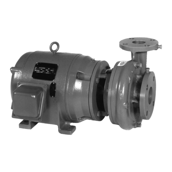
Product Description Product Description General description The Series 1531 pump is a centrifugal, close-coupled pump. These features make the pump easy to install, operate, and service: • High efficiency • Rugged bronze-fitted construction • Foot-mounted motor Intended applications WARNING: California Proposition 65 warning! This product contains chemicals known to the state of California to cause cancer and birth defects or other reproductive harm. - Page 12 Product Description Seal type Parameter Value Packing pH range pH 7–9 Liquid temperature range 0˚F to 200˚F (-18˚C to 93˚C) Table notes An external flush is required on low pressure systems that contain a high concentration of abrasives. Use packing on open or closed systems which require a large amount of makeup water, as well as systems that are subjected to a wide variety of chemical conditions and solids buildup.
-
Page 13: Installation
(See the nameplate on the drive unit to select properly-sized overloads.) NOTICE: Supervision by an authorized ITT representative is recommended to ensure proper installation. Failure to do so may result in equipment damage or decreased performance. -
Page 14: Foundation Requirements
Installation Guideline Explanation/comment Take into consideration the occurrence of unwanted The best pump location for noise and vibration noise and vibration. absorption is on a concrete floor with subsoil underneath. If the pump location is overhead, undertake special Consider a consultation with a noise specialist. precautions to reduce possible noise transmission. - Page 15 Installation Check Explanation/comment Checked Check that the suction and discharge pipes are This eliminates pipe strain on the pump . supported independently by use of pipe hangers near the pump . Check that there is a strong, rigid support for the As a rule, ordinary wire or band hangers are suction and discharge lines.
-
Page 16: Typical Installation
Installation Typical installation Compression tank (located in the suction piping) Rolairtrol air separator System supply Circuit setter Triple duty valve Pump Suction diffuser Isolation valve Pipe from boiler, chiller, or converter 10. Cold water supply 11. Reducing valve Series 1531 Installation, Operation, and Maintenance Manual... -
Page 17: Commissioning, Startup, Operation, And Shutdown
Commissioning, Startup, Operation, and Shutdown Commissioning, Startup, Operation, and Shutdown Preparation for startup WARNING: • Failure to follow these precautions before you start the unit will lead to serious personal injury and equipment failure. • Do not operate the pump below the minimum rated flows or with the suction or discharge valves closed. -
Page 18: Start The Pump
Commissioning, Startup, Operation, and Shutdown Start the pump CAUTION: • Observe the pump for vibration levels, bearing temperature, and excessive noise. If normal levels are exceeded, shut down the pump and resolve the issue. Before you start the pump, you must perform these tasks: •... -
Page 19: Shut Down The Pump
Commissioning, Startup, Operation, and Shutdown CAUTION: • Avoid excessive vibration levels. Excessive vibration levels can damage the bearings, stuffing box or seal chamber, and the mechanical seal, which can result in decreased performance. • Avoid increased radial load. Failure to do so can cause stress on the shaft and bearings. •... -
Page 20: Maintenance
Maintenance Maintenance Bearing maintenance Bearing lubrication schedule Type of bearing First lubrication Lubrication intervals Motor bearings No initial lubrication. The motor Refer to the motor manufacturer's was lubricated at the factory. recommendations for lubrication intervals. Disassembly Disassembly precautions WARNING: • This manual clearly identifies accepted methods for disassembling units. These methods must be adhered to. -
Page 21: Remove The Mechanical Seal (1531 And 1531-F)
Maintenance WARNING: Make certain that the internal pressure of the pump is relieved before you continue. Failure to follow these instructions could result in serious personal injury or death, or property damage. Remove the seal flushing tube if it is used. Remove the volute capscrews. - Page 22 Maintenance Assemble the standard mechanical seal (1531 and 1531-F) Lubricate the shaft sleeve and coverplate seal cavity with soapy water. Do not use a petroleum lubricant. Install a new cup gasket and a new seal insert with the indentation side down into the cup. Slide a new rotating seal assembly onto the shaft sleeve.
- Page 23 Maintenance O-ring Coverplate For 1-1/4 in. seal: 1-13/32 in. (3.571 cm) For 1-5/8 in. seal: 1-1/4 in. (3.175 cm) Seal locking collar Seal cap bolt Seal cap O-ring Motor end Figure 2: Single mechanical seal (1531–S) Assemble the double mechanical seal (1531-D) Lubricate the shaft sleeve, seal cap, and coverplate cavity with soapy water.
-
Page 24: Assemble The Packed Stuffing Box (1531-Pf)
Maintenance Replace the seal cap gasket. Slide the rotating portion of the seal assembly onto the shaft sleeve. Assemble the coverplate onto the bracket. Tighten the capscrews according to the Capscrew torque values table. Attach the seal cap to the coverplate. 10. -
Page 25: Capscrew Torque Values
180 (244) 325 (441) 525 (712) 800 (1085) Dealer servicing If trouble occurs that cannot be rectified, contact your local ITT representative and be prepared to provide this information: Complete nameplate data of pump and motor Suction and discharge pipe pressure gauge readings... - Page 28 ITT - Bell & Gossett 8200 N. Austin Avenue Morton Grove, IL 60053 Tel. 1-847-966-3700 Fax 1-847-966-9052 © 2009 ITT Corporation. The original instruction is in English. All non-English instructions are translations of the original instruction. P81567_E_ 1 .0_en.US_2011 -01_IOM.1531...
Need help?
Do you have a question about the Bell & Gossett 1531 Series and is the answer not in the manual?
Questions and answers