Table of Contents
Advertisement
Quick Links
Advertisement
Table of Contents

Related Manuals for ITT Goulds Pump 3355


Summary of Contents for ITT Goulds Pump 3355
- Page 1 Installation, Operation, and Maintenance Manual Model 3355...
-
Page 3: Table Of Contents
Table of Contents Table of Contents 1 Introduction and Safety ............................ 4 1.1 Introduction..............................4 1.1.1 Requesting other information ......................4 1.2 Safety ................................ 4 1.2.1 Safety terminology and symbols ..................... 5 1.2.2 Environmental safety........................6 1.2.3 User safety ............................6 1.2.4 Ex-approved products ........................ - Page 4 Table of Contents 4.5.3 Suction-piping checklist......................... 33 4.5.4 Discharge piping checklist......................34 4.5.5 Final piping checklist ........................35 5 Commissioning, Startup, Operation, and Shutdown ................... 36 5.1 Preparation for startup..........................36 5.2 Remove the coupling guard ........................37 5.3 Check the rotation ........................... 38 5.4 Couple the pump and driver ........................
- Page 5 Table of Contents 6.7.3 Nozzle loads..........................58 6.7.4 Recommended minimum flows ..................... 59 6.7.5 Wearing parts and dimensions...................... 60 7 Troubleshooting .............................. 61 7.1 Alignment troubleshooting........................61 7.2 Operation troubleshooting ........................61 8 Parts Listings and Cross-sectional Drawings ....................67 8.1 Recommended spare parts ........................
-
Page 6: Introduction And Safety
For instructions, situations, or events that are not consid- ered in this manual or in the sales documents, please contact the nearest ITT representative. Always specify the exact product type and identification code when requesting technical information or spare parts. -
Page 7: Safety Terminology And Symbols
Risk of injury and/or property damage. Operating a pump in an inappropriate application can cause over pressurization, overheating, and/or unstable operation. Do not change the service application without the approval of an authorized ITT representative. 1.2.1 Safety terminology and symbols... -
Page 8: Environmental Safety
WARNING: If the product has been contaminated in any way, such as from toxic chemicals or nuclear radi- ation, do NOT send the product to ITT until it has been properly decontaminated and advise ITT of these conditions before returning. -
Page 9: Ex-Approved Products
1.2 Safety • Always bear in mind the risk of drowning, electrical accidents, and burn injuries. Safety equipment Use safety equipment according to the company regulations. Use this safety equipment within the work area: • Helmet • Safety goggles, preferably with side shields •... -
Page 10: Description Of Atex
Compliance is fulfilled only when you operate the unit within its intended use. Do not change the condi- tions of the service without the approval of an ITT representative. When you install or maintain explosion proof products, always comply with the directive and applicable standards (for example, IEC/EN 60079–... - Page 11 All service and repair work is done by ITT-authorized personnel. • Genuine ITT parts are used. • Only Ex-approved spare parts and accessories authorized by ITT are used in Ex-approved prod- ucts. Limitations The warranty does not cover faults caused by these situations: •...
-
Page 12: Transportation And Storage
2 Transportation and Storage 2 Transportation and Storage 2.1 Inspect the delivery 2.1.1 Inspect the package Inspect the package for damaged or missing items upon delivery. Note any damaged or missing items on the receipt and freight bill. File a claim with the shipping company if anything is out of order. If the product has been picked up at a distributor, make a claim directly to the distributor. -
Page 13: Storage Guidelines
2.3 Storage guidelines Precautions for lifting the pump WARNING: • Dropping, rolling or tipping units, or applying other shock loads, can cause property dam- age and/or personal injury. Ensure that the unit is properly supported and secure during lifting and handling. •... -
Page 14: Storage Location
You can purchase long-term storage treatment with the initial unit order or you can purchase it and apply it after the units are already in the field. Contact your local ITT sales representative. Model 3355 Installation, Operation, and Maintenance Manual... -
Page 15: Product Description
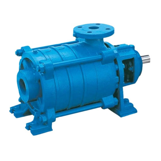
3 Product Description 3 Product Description 3.1 General description The Goulds Model 3355 is a radially-split, segmented casing, multistage pump that is designed with modular interstage components. This pump is manufactured in cast iron and 316 stainless steel. This pump can be configured in two ways: •... -
Page 16: Part Description
3.1 General description 3.1.1 Part description Casing The pump consists of three pressure boundary parts: • Suction casing - available in an end suction (ES) or radial suction (RS) configuration The suction casing has 150 or 300 lb. flanges and the discharge casing has 300 or 600 lb. flanges. •... -
Page 17: Nameplate Information
3.2 Nameplate information Couplings The standard baseplate design facilitates non−spacer couplings. Coupling guard Steel coupling guards are available and are designed to comply with OSHA requirements. 3.2 Nameplate information Important information for ordering Every pump has a nameplate that provides information about the pump. The nameplate is located on the pump casing. - Page 18 3.2 Nameplate information Nameplate field Explanation Rated pump flow, in gallons per minute FT HD Rated pump head, in feet Rated pump speed, revolutions per minute MOD. Pump model SIZE Size of the pump STD. NO. ANSI standard designation MAT L. CONST. Material of which the pump is constructed SER.
- Page 19 Use of equipment unsuitable for the environment can pose risks of ignition and/or explosion. Ensure the pump driver and all other auxiliary components meet the required area classifica- tion at the site. If they are not compatible, do not operate the equipment and contact an ITT representative before proceeding.
-
Page 20: Installation
Electrical connections must be made by certified electricians in compliance with all inter- national, national, state and local regulations. • Supervision by an authorized ITT representative is recommended to ensure proper instal- lation. Improper installation may result in equipment damage or decreased performance. 4.1.1 Pump location guidelines... -
Page 21: Foundation Requirements
4.1 Pre-installation 4.1.2 Foundation requirements Requirements • The location and size of the foundation bolt holes must match those shown on the assembly draw- ing provided with the pump data package. • The foundation must weigh between two and three times the weight of the complete pump, base- plate, and drive assembly. -
Page 22: Baseplate-Mounting Procedures
4.2 Baseplate-mounting procedures 4.2 Baseplate-mounting procedures 4.2.1 Prepare the baseplate for mounting Remove all the attached equipment from the baseplate. Clean the underside of the baseplate completely. If applicable, coat the underside of the baseplate with an epoxy primer. Use an epoxy primer only if using an epoxy-based grout. Remove the rust-proofing coat from the machined mounting pads using an appropriate solvent. - Page 23 4.2 Baseplate-mounting procedures Cut the plates from the bar stock and chamfer the edges of the plates in order to reduce stress concentrations. Put the plates between the jackscrews and the foundation surface. Use the four jackscrews in the corners in order to raise the baseplate above the foundation. Make sure that the center jackscrews do not touch the foundation surface yet.
-
Page 24: Install The Baseplate Using Spring Mounting
4.2 Baseplate-mounting procedures Hand-tighten the nuts for the foundation bolts. Check that the driver's mounting pads are level and adjust the jackscrews and the foundation bolts if necessary. 4.2.4 Install the baseplate using spring mounting NOTICE: The spring-mounted baseplate is designed only to support piping loads from thermal expan- sion. -
Page 25: Install The Baseplate Using Stilt Mounting
4.2 Baseplate-mounting procedures Upper jam nut Follower Washer Foundation pads Spring Upper adjusting nut Spring stud Figure 10: Example of an installed spring assembly 4.2.5 Install the baseplate using stilt mounting NOTICE: The stilt-mounted baseplate is not designed to support static piping loads. Ensure that the suc- tion and discharge piping are supported individually. - Page 26 4.2 Baseplate-mounting procedures Lower the baseplate so that the stilts fit into the foundation cups. Level the baseplate and make the final height adjustments: Loosen the upper jam nuts and adjusting nuts. Adjust the height and level the baseplate by moving the lower adjusting nuts. When the baseplate is level, tighten the top adjusting nuts.
-
Page 27: Baseplate-Leveling Worksheet
4.2 Baseplate-mounting procedures 4.2.6 Baseplate-leveling worksheet Level measurements 1)____________________ 2)____________________ 3)____________________ 4)____________________ 5)____________________ 6)____________________ 7)____________________ 8)____________________ 9)____________________ 10)___________________ 11)___________________ 12)___________________ 13)___________________ 14)___________________ 15)___________________ 16)___________________ 17)___________________ 18)___________________ Model 3355 Installation, Operation, and Maintenance Manual... -
Page 28: Pump-To-Driver Alignment
4.3 Pump-to-driver alignment 4.3 Pump-to-driver alignment Precautions WARNING: • Failure to disconnect and lock out driver power may result in serious physical injury or death. Always disconnect and lock out power to the driver before performing any installa- tion or maintenance tasks. •... -
Page 29: Permitted Indicator Values For Alignment Checks
The correct tolerances must be used. Failure to do so can result in misalignment. Contact ITT for further information. When dial indicators are used to check the final alignment, the pump and drive unit are correctly aligned when these conditions are true: •... - Page 30 4.3 Pump-to-driver alignment When the Then... reading val- ue is... Negative The coupling halves are farther apart at the bottom than at the top. Perform one of these steps: • Add shims in order to raise the feet of the driver at the shaft end. •...
-
Page 31: Grout The Baseplate
The specified permitted reading values are valid only at operating temperature. For cold set- tings, other values are permitted. The correct tolerances must be used. Failure to do so can result in misalignment. Contact ITT for further information. 4.3.5.4 Perform parallel alignment for a horizontal correction A unit is in parallel alignment when the parallel indicator (P) does not vary by more than as measured at four points 90°... - Page 32 4.4 Grout the baseplate Clean all the areas of the baseplate that will come into contact with the grout. Build a dam around the foundation. Thoroughly wet the foundation that will come into contact with the grout. Pour grout through the grout hole into the baseplate up to the level of the dam. When you pour the grout, remove air bubbles from it by using one of these methods: •...
-
Page 33: Piping Checklists
4.5 Piping checklists 4.5 Piping checklists 4.5.1 Fastening WARNING: Risk of serious personal injury or property damage. Fasteners such as bolts and nuts are criti- cal to the safe and reliable operation of the product. Ensure appropriate use of fasteners during installation or reassembly of the unit. - Page 34 4.5 Piping checklists NOTICE: Vary the capacity with the regulating valve in the discharge line. Never throttle the flow from the suction side. This action can result in decreased performance, unexpected heat generation, and equipment damage. Piping guidelines Guidelines for piping are given in the Hydraulic Institute Standards available from the Hydraulic Institute at 9 Sylvan Way, Parsippany, NJ 07054-3802.
-
Page 35: Suction-Piping Checklist
4.5 Piping checklists 4.5.3 Suction-piping checklist Performance curve reference Net positive suction head available (NPSH ) must always exceed NPSH required (NPSH ) as shown on the published performance curve of the pump. Suction-piping checks Check Explanation/comment Checked Check that the distance between the inlet This minimizes the risk of cavitation in the suction in- flange of the pump and the closest elbow let of the pump due to turbulence. -
Page 36: Discharge Piping Checklist
4.5 Piping checklists Check Explanation/comment Checked Check that the suction piping slopes up- — wards from the liquid source to the pump inlet. If the pump is not self-priming, check that a Use a foot valve with a diameter that is at least equiva- device for priming the pump is installed. -
Page 37: Final Piping Checklist
4.5 Piping checklists 4.5.5 Final piping checklist Check Explanation/comment Checked Check that the shaft rotates smoothly. Rotate the shaft by hand. Make sure there is no rubbing that can lead to excess heat generation or sparks. Re-check the alignment to make sure that If pipe strain exists, then correct the piping. -
Page 38: Commissioning, Startup, Operation, And Shutdown
5 Commissioning, Startup, Operation, and Shutdown 5 Commissioning, Startup, Operation, and Shutdown 5.1 Preparation for startup WARNING: • Risk of serious physical injury or death. Exceeding any of the pump operating limits (e.g. - pressure, temperature, power, etc.) could result in equipment failure, such as explosion, seizure, or breach of containment. -
Page 39: Remove The Coupling Guard
5.2 Remove the coupling guard • Risk of explosive hazard and premature failure from sparks and heat genera- tion. Ensure bearings are properly lubricated prior to startup. • Risk of seizure, breach of containment, or explosion. Ensure balance line is installed and piped back to either the pump suction or suction vessel. -
Page 40: Check The Rotation
5.3 Check the rotation Lift upwards. Remove the remaining nut, bolt, and washers from the pump half of the coupling guard. It is not necessary to remove the end plate from the pump side of the bearing housing. You can access the bearing-housing tap bolts without removing this end plate if maintenance of internal pump parts is necessary. -
Page 41: Couple The Pump And Driver
5.4 Couple the pump and driver Make sure that the coupling hubs are fastened securely to the shafts. Unlock power to the driver. Make sure that everyone is clear, and then jog the driver long enough to determine that the direc- tion of rotation corresponds to the arrow on the bearing housing or close-coupled frame. -
Page 42: Install The Coupling Guard
5.4 Couple the pump and driver 1/2 x .XX 1/2 x .XX Sleeve bearing Thrust collar Coupling Figure 15: Driver shaft centering Use the instructions from the coupling manufacturer to lubricate and install the coupling. Check the angular and parallel alignment of the coupling halves. See Pump-to-driver alignment in the Installation chapter. - Page 43 5.4 Couple the pump and driver Item Description Annular groove Pump-side end plate Driver Pump half of the coupling guard Figure 16: Guard half installation The annular groove in the coupling guard half must fit around the end plate. Item Description Annular groove End plate (pump end) Guard half...
-
Page 44: Pump Priming
5.5 Pump priming Item Description Washer Bolt Figure 18: Secure coupling guard half to end plate Put the driver half of the coupling guard in place: Slightly spread the bottom apart. Place the driver half of the coupling guard over the pump half of the coupling guard. The annular groove in the coupling guard half must face the motor. -
Page 45: Other Methods Of Priming The Pump
5.6 Start the pump • Another outside supply Close the discharge isolation valve. Open the air vent valves in the casing. Open the air vents in the seal covers. Open the valve in the outside supply line until only liquid escapes from the vent valves. Close the vent valves. -
Page 46: Pump Operation Precautions
5.7 Pump operation precautions If the pump exceeds normal levels, then shut down the pump immediately and correct the prob- lem. Repeat steps 5 and 6 until the pump runs properly. 5.7 Pump operation precautions General considerations NOTICE: • Vary the capacity with the regulating valve in the discharge line. Never throttle the flow from the suction side. -
Page 47: Shut Down The Pump
5.8 Shut down the pump 5.8 Shut down the pump WARNING: Precautions must be taken to prevent physical injury. The pump may handle hazardous and/or toxic fluids. Proper personal protective equipment should be worn. Pumpage must be handled and disposed of in conformance with applicable environmental regulations. Slowly close the discharge valve. -
Page 48: Maintenance
6 Maintenance 6 Maintenance 6.1 Maintenance schedule Maintenance inspections A maintenance schedule includes these types of inspections: • Routine maintenance • Routine inspections • Three-month inspections • Annual inspections Shorten the inspection intervals appropriately if the pumped fluid is abrasive or corrosive or if the envi- ronment is classified as potentially explosive. -
Page 49: Bearing Maintenance
6.2 Bearing maintenance If the pump performance does not satisfy your process requirements, and the process requirements have not changed, then perform these steps: Disassemble the pump. Inspect it. Replace worn parts. 6.2 Bearing maintenance 6.2.1 Ball bearing types Grease lubricated bearings Pump size Suction side, radial suction Discharge side, radial and end suction 1.5 x 2.5-7 6306-C3 5306 A... -
Page 50: Regrease The Grease-Lubricated Bearings
Cartridge seals installed by the user require disengagement of the hold- ing clips prior to operation, allowing the seal to slide into place. If the seal has been installed in the pump by ITT, these clips have already been disengaged. Other mechanical seal types For other types of mechanical seals, refer to the instructions provided by the seal manufacturer for instal- lation and setting. -
Page 51: Disassembly
6.4 Disassembly Reference drawing The manufacturer supplies a reference drawing with the data package. Keep this drawing for future use when you perform maintenance and seal adjustments. The seal drawing specifies the required flush fluid and attachment points. Before you start the pump Check the seal and all flush piping. -
Page 52: Tools Required
6.4 Disassembly • Risk of physical injury from hot bearings. Wear insulated gloves when using a bearing heater. 6.4.2 Tools required In order to disassemble the pump, you need these tools: • Bearing puller • Cleaning agents and solvents • Dial indicators •... -
Page 53: Disassemble The Pump Body
6.4 Disassembly Remove the flinger guards (499) if applicable. Place the pump in a horizontal position. Raise the discharge casing (100D) with wooden blocks so that the feet of the bearing bracket (228C) are exposed by approximately 0.50 in. (1.27 cm). Move back the thrower (248) or heat flinger (123B) if applicable. -
Page 54: Preassembly Inspections
6.5 Preassembly inspections Remove bearing cover (119), spacer sleeve (157) and thrower (248) or heat flinger (123B) if appli- cable. Remove shaft sleeve key (401). Remove seal cover (184). Pre-treat fitting surface between the seal cover and the casing with com- patible lubricant. -
Page 55: Reassemble The Shaft Seal
6.6 Reassembly 6.6.2 Reassemble the shaft seal CAUTION: Placing the pump in a vertical position is required for assembly. Always use a lubricant when mounting mechanical seals. Do not use mineral grease or oil if you are not absolutely certain that it is compatible with the O-ring material. Insert the seat ring of the mechanical seal (383 &... -
Page 56: Reassemble The Pump Body
6.6 Reassembly Clean and lubricate the fitting surfaces between the bearing bracket (228C) and suction casing (110F). Preheat the new bearing (112) to a maximum of 230°F (110°C) and slide it onto the shaft (122). Tighten the new shaft nut (136A) while the bearing is still hot, then turn it back one quarter of a turn. After the bearing cools down, pack the bearing completely with grease making sure that grease gets under the cage. -
Page 57: Complete The Reassembly For The End Suction Configuration
6.6 Reassembly 10. For the RS configuration, assemble the pump down to the suction casing (100F) For the RS configuration, slide on the sleeve (310) and mount the suction casing (100F) with the O- ring (312F). Make sure that the lines are in the correct position. 6.6.5 Complete the reassembly for the end suction configuration Slide on the bearing sleeve (310) and lubricate the bearing surface. -
Page 58: Assembly References
6.7 Assembly references 10. Place the pre-mounted unit on the discharge casing (100D) and tighten the nuts (425) firmly. See the Torque values table. Rotate the shaft (122) in order to make sure that it turns freely. 12. Mount the coupling half. You might need to preheat to a maximum of 230°F (110°C). 6.7 Assembly references 6.7.1 Torque values Table 3: Maximum torque values, in ft-lbs (Nm) for 1.5 x 2.5-7 and 2.5 x 4-8 pumps... - Page 59 6.7 Assembly references Area B - Gap between the impeller hub and diffuser Pump size Nominal diameter Gap "new" (inches) Maximum permissible gap All iron and stainless fitted Stainless steel Minimum Maximum Minimum Maximum 1.5 x 2.5-7 1.496 0.006 0.008 0.012 0.014 0.020...
-
Page 60: Nozzle Loads
6.7 Assembly references 6.7.3 Nozzle loads Direction of forces • Fx = force along the x - axis • Fy = force along the y - axis • Fz = force along the z - axis Direction of moments • Mx = moment around the x - axis •... -
Page 61: Recommended Minimum Flows
6.7 Assembly references Nozzle configuration Flange Forces in lbf (N) Moments in ft-lbs (Nm) size (in) Σ F Σ M 126 (560) 115 (510) 139 (620) 220 (980) 258 (350) (200) (260) (480) 202 (900) 182 (810) 227 (1010) (1580) (440) (260) (330) -
Page 62: Wearing Parts And Dimensions
6.7 Assembly references 6.7.5 Wearing parts and dimensions Radial suction End suction Model 3355 Installation, Operation, and Maintenance Manual... -
Page 63: Troubleshooting
7 Troubleshooting 7 Troubleshooting 7.1 Alignment troubleshooting Symptom Cause Remedy Horizontal (side-to-side) align- The driver feet are bolt- Loosen the pump's hold-down bolts, and slide the pump ment cannot be obtained (angu- bound. and driver until you achieve horizontal alignment. lar or parallel). - Page 64 7.2 Operation troubleshooting Symptom Cause Remedy Check that the suction pipe is vacuum- tight. Provide valves and fittings in the suction pipe with water seal. The direction of rotation is wrong. Change the motor rotation. The inner components are suffering Replace the worn parts.
- Page 65 7.2 Operation troubleshooting Symptom Cause Remedy Check that the suction pipe is vacuum- tight. Provide valves and fittings in the suction pipe with water seal. The direction of rotation is wrong. Change the motor rotation. The inner components are suffering Replace the worn parts.
- Page 66 7.2 Operation troubleshooting Symptom Cause Remedy Forces in the pipeline are too high and Change the position of the support pipes the pump is under strain. and use compensators. Check that the foundation plate and frame are properly cast and in place. There is too much, not enough, or the Change the lubricant.
- Page 67 7.2 Operation troubleshooting Symptom Cause Remedy When you adjust the speed (frequency transformer), check the reference value setting. The inner components are suffering Replace the worn parts. from wear. The forces in the pipeline are too high Change the position of the support pipes and the pump is under strain.
- Page 68 7.2 Operation troubleshooting Symptom Cause Remedy Replace the mechanical seal. Model 3355 Installation, Operation, and Maintenance Manual...
-
Page 69: Parts Listings And Cross-Sectional Drawings
8 Parts Listings and Cross-sectional Drawings 8 Parts Listings and Cross-sectional Drawings 8.1 Recommended spare parts Select spare parts that will last for two years of continuous operation. If no other guidelines are applica- ble, stock the number of parts listed in this table. Spare part Number of pumps (includes stand-by pumps) 10 or more... -
Page 70: Radial Suction All-Iron Cross-Sectional
8.2 Radial suction all-iron cross-sectional 8.2 Radial suction all-iron cross-sectional Model 3355 Installation, Operation, and Maintenance Manual... -
Page 71: Radial Suction All Iron With Stainless Steel Impeller Cross Sectional
8.3 Radial suction all iron with stainless steel impeller cross sectional 8.3 Radial suction all iron with stainless steel impeller cross sectional Model 3355 Installation, Operation, and Maintenance Manual... -
Page 72: Radial Suction Stainless Steel Cross-Sectional
8.4 Radial suction stainless steel cross-sectional 8.4 Radial suction stainless steel cross-sectional Model 3355 Installation, Operation, and Maintenance Manual... -
Page 73: End-Suction All-Iron Cross-Sectional
8.5 End-suction all-iron cross-sectional 8.5 End-suction all-iron cross-sectional Model 3355 Installation, Operation, and Maintenance Manual... -
Page 74: End-Suction All-Iron With Stainless Steel Impeller Cross-Sectional
8.6 End-suction all-iron with stainless steel impeller cross-sectional 8.6 End-suction all-iron with stainless steel impeller cross- sectional Model 3355 Installation, Operation, and Maintenance Manual... -
Page 75: End-Suction Stainless Steel Cross-Sectional
8.7 End-suction stainless steel cross-sectional 8.7 End-suction stainless steel cross-sectional Model 3355 Installation, Operation, and Maintenance Manual... -
Page 76: Radial Suction (Counterclockwise Rotation) All-Iron Cross-Sectional
8.8 Radial suction (counterclockwise rotation) all-iron cross-sectional 8.8 Radial suction (counterclockwise rotation) all-iron cross- sectional Model 3355 Installation, Operation, and Maintenance Manual... -
Page 77: Radial Suction (Counterclockwise Rotation) All-Iron With Stainless Steel Impeller Cross-Sectional
8.9 Radial suction (counterclockwise rotation) all-iron with stainless steel impeller cross-sectional 8.9 Radial suction (counterclockwise rotation) all-iron with stainless steel impeller cross-sectional Model 3355 Installation, Operation, and Maintenance Manual... -
Page 78: Radial Suction (Counterclockwise Rotation) Stainless Steel Cross-Sectional
8.10 Radial suction (counterclockwise rotation) stainless steel cross-sectional 8.10 Radial suction (counterclockwise rotation) stainless steel cross-sectional Model 3355 Installation, Operation, and Maintenance Manual... - Page 79 Visit our website for the latest version of this document and more information: http://www.gouldspumps.com Goulds Pumps 240 Fall Street Seneca Falls, NY Form IOM.3355.en-US.2021-03 ©2021 ITT Corporation The original instruction is in English. All non-English instructions are translations of the original instruction.
Need help?
Do you have a question about the Goulds Pump 3355 and is the answer not in the manual?
Questions and answers