Advertisement
Quick Links
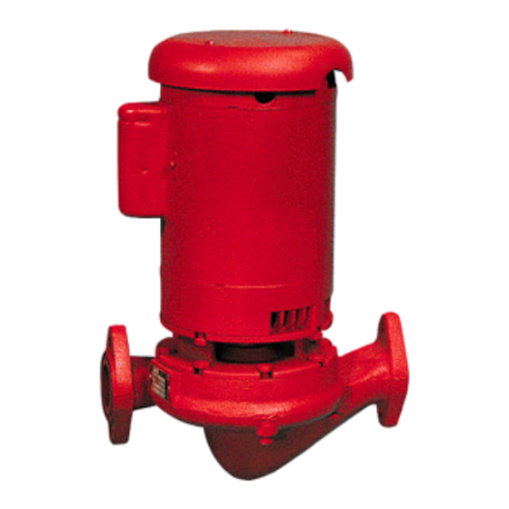
Series 90 In-Line Centrifugal Pump
Installation, Operation & Service Instructions
INSTALLER:
DESCRIPTION
The Series 90 In-Line Mounted Centrifugal Pump is a close
coupled, space saving, low maintenance pump capable of
performing a wide range of fluid applications. The Back Pull-
Out feature allows the pump to be serviced without disturbing
system piping. The Series 90 pumps are available for pipe
sizes from 1" to 2".
PUMP
APPLICATION
Series90 Pumps may be used for
ing, domestic hot water, cooling towers, machinery cooling,
pressure boosting, industrial fluid transfer, refrigeration and
heater exchanger circulation. Bell & Gossett recommends that
bronze constructed pumps be used for pumping potable
water. For other applications contact your local Bell & Gossett
representative.
PLEASE
LEAVE THIS MANUAL FOR THE OWNER'S USE.
hydronic heating and cool-
Bell & Gossett
Instruction Manual P81547
OPERATIONAL LIMITS
Bell &
Gossett Series 90 Pumps are designed to pump liquids
compatible with their iron or bronze body construction.
Unless special provisions have been made by ITT Bell &
Gossett, the operational limits for Series 90 Pumps are listed
below.
Do not exceed these values.
Maximum
Working Pressure: 175 psi
Mechanical Seal: BUNA – PH Limitations 7-9;
Temperature Range –20 to +225°F
EPT –
PH Limitations 7-11;
Temperature Range –20 to +250°F
®
REVISION B
Advertisement

Related Manuals for ITT Bell & Gossett 90 Series


Summary of Contents for ITT Bell & Gossett 90 Series
- Page 1 The Back Pull- Unless special provisions have been made by ITT Bell & Out feature allows the pump to be serviced without disturbing Gossett, the operational limits for Series 90 Pumps are listed system piping.
-
Page 2: Additional Safety Requirements
SAFETY SAFETY REQUIREMENTS INSTRUCTIONS ELECTRICAL SAFETY: This safety alert symbol will be used in this manual and on WARNING: ELECTRICAL SHOCK HAZARD pump instruction decals to draw attention to safety related Electrical connections to be made by a qualified elec- instructions. -
Page 3: Schematic Example
PUMP LOCATION Install the suction and discharge flanges on the pipe ends using teflon tape sealer or high quality thread sealant. Minimize PUMP SUPPORT AND LOCATION strain on the pump by supporting the suction and discharge piping with pipe hangers near the pump. Line up the vertical The Bell &... -
Page 4: Operational Instructions
WIRING INSTRUCTIONS The pump should be started with the discharge valve closed and the suction valve fully open. After the pump is at operating speed, the discharge valve should be opened gradually. WARNING: ELECTRICAL SHOCK HAZARD Disconnect and lockout the power before making SERVICE INSTRUCTIONS electrical connections. - Page 5 DETERMINE THE SEAL SIZE 2. Lift the spring retainer (not found in the 1 " seal assem- bly) and the seal spring from the shaft. Remove the com- Cut away diagrams have been provided to illustrate the com- pression ring from the seal collar by inserting a small ponents of the Series 90 Pump assemblies.
- Page 6 © COPYRIGHT 2007 BY 8200 N. Austin Avenue ITT CORPORATION Morton Grove, IL 60053 PRINTED IN U.S.A. 6-07 Phone: (847) 966-3700 THE ITT ENGINEERED BLOCKS SYMBOL AND Fax: (847) 966-9052 ENGINEERED FOR LIFE ARE REGISTERED www.bellgossett.com TRADEMARKS OF ITT CORPORATION...
Need help?
Do you have a question about the Bell & Gossett 90 Series and is the answer not in the manual?
Questions and answers