Table of Contents
Advertisement
Quick Links
Advertisement
Table of Contents

Related Manuals for ITT GOULDS PUMPS 3408


Summary of Contents for ITT GOULDS PUMPS 3408
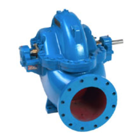
- Page 1 Installation, Operation, and Maintenance Manual Model 3408...
-
Page 3: Table Of Contents
Table of Contents Table of Contents 1 Introduction and Safety ............................ 4 1.1 Introduction..............................4 1.1.1 Requesting other information ......................4 1.2 Safety ................................ 4 1.2.1 Safety terminology and symbols ..................... 5 1.2.2 Environmental safety........................6 1.2.3 User safety ............................7 1.2.4 Safety regulations for Ex-approved products in potentially explosive atmospheres ....... - Page 4 6.9 Spare parts.............................. 80 7 Troubleshooting .............................. 81 7.1 Troubleshooting............................81 8 Parts List and Cross-Sectionals ........................84 8.1 Exploded views ............................84 8.2 Parts list..............................86 9 Local ITT Contacts ............................88 Model 3408 Installation, Operation, and Maintenance Manual...
- Page 5 Table of Contents 9.1 Regional offices............................88 Model 3408 Installation, Operation, and Maintenance Manual...
-
Page 6: Introduction And Safety
For instructions, situations, or events that are not consid- ered in this manual or in the sales documents, please contact the nearest ITT representative. Always specify the exact product type and serial number when requesting technical information or spare parts. -
Page 7: Safety Terminology And Symbols
Risk of injury and/or property damage. Operating a pump in an inappropriate application can cause over pressurization, overheating, and/or unstable operation. Do not change the service application without the approval of an authorized ITT representative. WARNING: This product contains Carbon Black a chemical known to the State of California to cause can- cer. -
Page 8: Environmental Safety
WARNING: If the product has been contaminated in any way, such as from toxic chemicals or nuclear radi- ation, do NOT send the product to ITT until it has been properly decontaminated and advise ITT of these conditions before returning. -
Page 9: User Safety
1.2 Safety 1.2.3 User safety General safety rules These safety rules apply: • Always keep the work area clean. • Pay attention to the risks presented by gas and vapors in the work area. • Avoid all electrical dangers. Pay attention to the risks of electric shock or arc flash hazards. •... - Page 10 1.2 Safety 1.2.3.1 Precautions before work Observe these safety precautions before you work with the product or are in connection with the product: • Provide a suitable barrier around the work area, for example, a guard rail. • Make sure that all safety guards are in place and secure. •...
-
Page 11: Safety Regulations For Ex-Approved Products In Potentially Explosive Atmospheres
ITT disclaims all responsibility for work done by untrained and unauthorized personnel. These are the personnel requirements for Ex-approved products in potentially explosive atmospheres: • All work on the product must be carried out by certified electricians and ITT-authorized mechanics. Special rules apply to installations in explosive atmospheres. •... - Page 12 • Maintain proper bearing lubrication. • Do not modify the equipment without approval from an authorized ITT representative. • Only use parts that have been provided by an authorized ITT representative. All pumping unit (pump, seal, coupling, motor and pump accessories) certified for use in an ATEX classi- fied environment, are identified by an ATEX tag secured to the pump or baseplate on which it is mount- ed.
-
Page 13: Monitoring Equipment
All service and repair work is done by ITT-authorized personnel. • Genuine ITT parts are used. • Only Ex-approved spare parts and accessories authorized by ITT are used in Ex-approved prod- ucts. Limitations The warranty does not cover faults caused by these situations: •... -
Page 14: Transportation And Storage
2 Transportation and Storage 2 Transportation and Storage 2.1 Inspect the delivery 2.1.1 Inspect the package Inspect the package for damaged or missing items upon delivery. Note any damaged or missing items on the receipt and freight bill. File a claim with the shipping company if anything is out of order. If the product has been picked up at a distributor, make a claim directly to the distributor. - Page 15 2.2 Transportation guidelines Pumps mounted horizontally Pump mounting Lifting method A bare pump Place a nylon sling, chain, or wire rope around both bearing housings. A pump mounted on a base that has WARNING: lifting holes If the driver has been mounted on the baseplate at the factory, then it is safe to lift the entire assembly.
-
Page 16: Storage Guidelines
2.3 Storage guidelines Pumps mounted vertically Pump mounting Lifting method Half pedestal Place a nylon sling chain or wire rope around both flanges. Use a latch hook or standard shackle and end loops. Be sure the lifting equipment is long enough to keep the lift angle less than 30°... - Page 17 You can purchase long-term storage treatment with the initial unit order or you can purchase it and apply it after the units are already in the field. Contact your local ITT sales representative. Model 3408 Installation, Operation, and Maintenance Manual...
-
Page 18: Product Description
Use of equipment unsuitable for the environment can pose risks of ignition and/or explosion. Ensure the pump driver and all other auxiliary components meet the required area classifica- tion at the site. If they are not compatible, do not operate the equipment and contact an ITT representative before proceeding. -
Page 19: Nameplate Information
3.2 Nameplate information Casing rings • Made of bronze, cast iron, or Nitronic 60 stainless steel • Installed with an anti-rotation device • Designed to restrict leakage across the ring fit Bearings • Grease lubricated or oil lubricated • Inboard, or coupling end, bearing: single row ball bearing •... - Page 20 3.2 Nameplate information When you order spare parts, identify this pump information: • Model • Size • Serial number • Item numbers of the required parts Item numbers can be found in the spare parts list. Refer to the nameplate on the pump casing for most of the information. See Parts List for item numbers. Nameplate types Nameplate Description...
- Page 21 3.2 Nameplate information Nameplate on the pump casing using metric units Figure 7: Metric units - nameplate on pump casing Table 3: Explanation of the nameplate on the pump casing Nameplate field Explanation IMPLR. DIA. Impeller diameter MAX. DIA. Maximum impeller diameter Rated pump flow, in cubic meters per hour M HD Rated pump head, in meters...
- Page 22 Use of equipment unsuitable for the environment can pose risks of ignition and/or explosion. Ensure the pump driver and all other auxiliary components meet the required area classifica- tion at the site. If they are not compatible, do not operate the equipment and contact an ITT representative before proceeding.
-
Page 23: Installation
Electrical connections must be made by certified electricians in compliance with all inter- national, national, state and local regulations. • Supervision by an authorized ITT representative is recommended to ensure proper instal- lation. Improper installation may result in equipment damage or decreased performance. 4.1.1 Pump location guidelines... -
Page 24: Foundation Requirements
4.1 Pre-installation Guideline Explanation/comment When possible, locate the pump below the fluid level. This facilitates priming, ensures a steady flow of liquid, and provides a positive suction head on the pump. Make sure there is a suitable power source available If the pump is motor-driven, then the electrical characteristics for the pump driver. -
Page 25: Set The Baseplate
4.2 Set the baseplate 4.2 Set the baseplate Pumps are checked at the factory for the ability to be aligned to the required tolerances. Due to the flexi- bility of an ungrouted base and handling in shipment, do not assume that the unit is in alignment when it is placed on the rough foundation. -
Page 26: Alignment Checks
4.3 Pump-to-driver alignment 4.3.1 Alignment checks When to perform alignment checks You must perform alignment checks under these circumstances: • The process temperature changes. • The piping changes. • The pump has been serviced. Types of misalignment Type of misalignment Description Angular misalignment Shafts have an axis concentric at the intersection but not parallel. -
Page 27: Align The Pump Using A Straight Edge
4.3 Pump-to-driver alignment 4.3.1.1 Cold settings for parallel vertical alignment Introduction This section shows the recommended preliminary (cold) settings for electric motor-driven pumps based on different temperatures of pumped fluid. Consult driver manufacturers for recommended cold settings for other types of drivers such as steam turbines and engines. Recommended settings Pumped fluid temperature Recommended setting for driver shaft Ambient... -
Page 28: Align The Pump Using A Dial Indicator
4.3 Pump-to-driver alignment Straight edge Feeler gauge Figure 13: Correct alignment 4.3.3 Align the pump using a dial indicator Before you begin, you must have a dial indicator with a mounting magnet and extension bars. A dial indicator can provide more accurate alignment than a straight edge. Fasten the indicator stand or magnetic base to the pump half of the coupling. -
Page 29: Grout The Baseplate
4.4 Grout the baseplate Dial indicator Reference mark Separator to take up the bearing slack Figure 15: Parallel alignment 4.4 Grout the baseplate CAUTION: Do not grout until the initial alignment is made. Grout compensates for an uneven foundation. Together with the baseplate, grout makes a very rigid in- terface between the pump and the foundation by distributing the weight over the length of the base and preventing shifting. -
Page 30: Piping Checklists
4.5 Piping checklists It will take approximately 24 hours for the grout to harden. Check the alignment. Approximately fourteen days after the grout has been poured and the grout has completely dried, apply an oil-based paint to the exposed edges of the grout in order to prevent air and moisture from coming in contact with the grout. - Page 31 4.5 Piping checklists Piping guidelines Guidelines for piping are given in the Hydraulic Institute Standards available from the Hydraulic Institute at 9 Sylvan Way, Parsippany, NJ 07054-3802. You must review this document before you install the pump. Checklist Check Explanation/comment Checked Check that all piping is supported in- •...
-
Page 32: Suction Piping Checklist
4.5 Piping checklists 4.5.2 Suction piping checklist The sizing and installation of the suction piping is extremely important. It must be selected and installed so that pressure losses are minimized and sufficient liquid flows into the pump when it is started and op- erated. - Page 33 4.5 Piping checklists This figure shows the unbalanced loading of a double-suction impeller due to the uneven flow around an el- bow that is adjacent to the pump: Pump casing Impeller Pump suction flange Suction elbow Water velocity increases here and causes a greater flow to one side of the impeller. Figure 17: Unbalanced loading of double-suction impeller Examples Level centerline of pipe...
- Page 34 4.5 Piping checklists Air pocket Figure 20: Suction pipe installed with a reducer – incorrect Air pocket Figure 21: Incorrect No air pockets Gradual rise Figure 22: Correct No air pockets Eccentric reducer Gradual rise Figure 23: Gradual rise to the pump – correct Distance plus eccentric reducer straightens the flow Figure 24: Suction pipe above the pump –...
-
Page 35: Suction-Piping Valve Considerations
4.5 Piping checklists 4.5.3 Suction-piping valve considerations Suction valves CAUTION: Never throttle the flow from the suction side. Only use suction valves to isolate the pump for maintenance, and install such valves in positions to avoid air pockets. Before you install suction valves in the suction piping, review these considerations: •... -
Page 36: Pressure Gauges
4.6 Pump doweling • Avoid high spots, such as loops. High spots will collect air and throttle the system or lead to erratic pumping. • A check valve and an isolating gate valve should be installed in the discharge line. •... -
Page 37: Commissioning, Startup, Operation, And Shutdown
5 Commissioning, Startup, Operation, and Shutdown 5 Commissioning, Startup, Operation, and Shutdown 5.1 Preparation for startup WARNING: • Failure to disconnect and lock out driver power may result in serious physical injury or death. Always disconnect and lock out power to the driver before performing any installa- tion or maintenance tasks. -
Page 38: Pump Priming
5.2 Pump priming • Check the driver lubrication. Refer to the driver Installation, Operation, and Maintenance manual. • Check that the pump bearings are properly lubricated. • If the pump is oil lubrication, check that the oil level is correct prior to starting pump. •... -
Page 39: Start The Pump
5.4 Start the pump Fill the system slowly so that excessive velocities do not cause rotation of the pumping elements. Rotation of the pumping elements can cause damage to the pump or its driver. Check the adequacy of the anchors and hangers: Mount a dial indicator off of any rigid structure not tied to the piping. -
Page 40: Shut Down The Pump
5.6 Shut down the pump Check Explanation/comment Checked Flow It is difficult to accurately measure flow rate (volume/time). Any of the fol- lowing methods of measuring can be used: • Venturi meters • Flow nozzles • Orifice plates • Timing the draw down in the wet well Record any reading for future reference. - Page 41 5.7 Freeze protection NOTICE: If heat is used to prevent the pump from freezing, then the temperature should not rise above 66°C | 150°F. Model 3408 Installation, Operation, and Maintenance Manual...
-
Page 42: Maintenance
6 Maintenance 6 Maintenance 6.1 Maintenance schedule CAUTION: Shorten the inspection intervals if the pumped liquid is abrasive or corrosive, or if the environ- ment is classified as potentially explosive. NOTICE: This timetable assumes that the unit has been constantly monitored after startup. Adjust the timetable for any extreme or unusual applications or conditions. -
Page 43: Flood-Damaged Pumps
These bearing lubrication sections list different temperatures of the pumped fluid. If the pump is ATEX- certified and the temperature of the pumped fluid exceeds the permitted temperature values, then con- sult your ITT representative. 6.3.1 Regrease the grease-lubricated bearings CAUTION: Grease-lubricated bearings are lubricated at the factory. - Page 44 6.3 Bearing maintenance Relief plug Fitting Figure 26: Grease lubricated bearings Wipe dirt from the grease fittings. Remove the two grease-relief plugs on the bearing housings. Fill both of the grease cavities through the fittings with a recommended grease until the fresh grease comes out of the relief holes.
-
Page 45: Lubricate The Oil-Lubricated Bearings
6.3 Bearing maintenance • Greases made from animal or vegetable oils are not recommended due to the danger of deteriora- tion and forming of acid. • Additional or replacement lubricant must be added after 2,000 hours or at three-month intervals. •... - Page 46 6.3 Bearing maintenance This ensures that the thumb screw will not interfere with setting the reservoir in the lower casting. 10. Place your thumb over the reservoir spout, invert the reservoir, and place it onto the lower casting while removing your thumb. Allow the reservoir to empty as it fills the bearing housing.
-
Page 47: Bearing Temperatures
6.3 Bearing maintenance 6.3.2.2 Level adjuster heights Pump size Dimension A Inboard Outboard 2x3-11 1.12 1.12 4x6-9 4x6-12 4x6-14 6x6-9 6x8-9 6x8-12 4x6-10 0.53 0.56 6x8-13 4x6-11 6x8-10 6x8-17 6x8-18 6x8-12M 8x8-12 8x8-17 1.22 0.53 8x10-12 8x10-17 10x10-12 10x12-12 10x12-14 10x12-17 8x10-20 10x12-18... -
Page 48: Coupling Lubrication
6.4 Shaft-seal maintenance 6.3.4 Coupling lubrication Flexible couplings Flexible couplings, such as Wood’s Sure-Flex or Falk Torus coupling, provide smooth transmission of power. There is no rubbing action of metal against rubber to cause wear. Couplings are not affected by abrasives, dirt, or moisture. -
Page 49: Mechanical Seal Maintenance
6.5 Disassembly Check or instruction Explanation/comment of the stuffing box. Then install each suc- ceeding ring. Stagger the joints at a 90° rota- tion. If a seal cage is supplied, check that it is The function of the seal cage is to establish a liquid seal around the properly located in the stuffing box under the shaft, to prevent leakage of air through the stuffing box, and to lubri- sealing water inlet. -
Page 50: Change The Rotation
6.5 Disassembly • Risk of serious physical injury or death from rapid depressurization. Ensure pump is iso- lated from system and pressure is relieved before disassembling pump, removing plugs, opening vent or drain valves, or disconnecting piping. • Risk of serious personal injury from exposure to hazardous or toxic liquids. A small amount of liquid will be present in certain areas like the seal chamber upon disassembly. -
Page 51: Remove The Upper Half Of The Casing
6.5 Disassembly With the rotating element out of the casing, remove the casing from the baseplate and turn the cas- ing 180°. Factory-supplied baseplates are drilled for both rotations. Put the rotating element back in the casing and reassemble the pump. The impeller and casing are in the same relationship to each other as they were originally. -
Page 52: Disassemble The Pump With Packing
6.5 Disassembly Figure 31: Rotating element 6.5.5 Disassemble the pump with packing Remove the four capscrews (3-904-9) from each bearing housing (3-025-3 and 3-025-4), and then remove the bearing housings from the shaft (3-007-0). Remove the bearings: Bend back the lockwasher tab and remove the locknut (3-516-4) and lockwasher (3-517-4) from the outboard end of the shaft. - Page 53 6.5 Disassembly O-ring Impeller Floating casing ring Casing O-ring Figure 33: Casing rings Loosen the setscrew (3-902-3) in the shaft nuts (3-015-9), and then remove the shaft nuts with a pin spanner wrench. Both shaft nuts have right-hand threads. Remove the O-rings (3-914-9) from the counterbore in the shaft sleeves. 10.
-
Page 54: Disassemble The Pump With Mechanical Seals On The Shaft
6.5 Disassembly 3-009-9 0-004-0 3-003-9 3-943-9 2-001-0 4-002-0 • 3-009-9: Sleeve • 0-004-4: Impeller ring • 3-003-9: Casing ring • 4-002-0: Impeller • 2-001-0: Casing • 3-943-9: Locking pin Figure 34: Impeller with replaceable rings 13. Remove the impeller key (3-911-1) from the shaft. 6.5.6 Disassemble the pump with mechanical seals on the shaft Remove the four capscrews (3-904-9) from each bearing housing (3-025-3 and 3-025-4), and then remove the bearing housings from the shaft (3-007-0). - Page 55 6.5 Disassembly Figure 35: Stuffing box removal Remove the lip seals (3-177-9) and O-rings (3-914-1) from the stuffing boxes. Drive both mechanical seal seats (3-401-0) from both the stuffing boxes. Remove the mechanical seal head (3-402-0) from the pump shaft. Remove the two casing rings (3-003-9) from the impeller (4-002-0), and then remove the O-rings (3-914-2) from each casing ring.
- Page 56 6.5 Disassembly Figure 36: Casing ring and O-ring removal Remove the impeller from the shaft as follows: Remove the impeller retaining ring (3-915-1) with retaining ring pliers. Heat the impeller hub on both ends to a maximum of 350°F (176°C), and then pull or push the impeller off the shaft.
-
Page 57: Disassemble The Pump With Mechanical Seals On The Shaft Sleeve
6.5 Disassembly 3-009-9 0-004-0 3-003-9 3-943-9 2-001-0 4-002-0 • 3-009-9: Sleeve • 0-004-4: Impeller ring • 3-003-9: Casing ring • 4-002-0: Impeller • 2-001-0: Casing • 3-943-9: Locking pin Figure 38: Impeller with replaceable rings 10. Remove the impeller key (3-911-1) from the shaft. 6.5.7 Disassemble the pump with mechanical seals on the shaft sleeve Remove the four capscrews (3-904-9) from each bearing housing (3-025-3 and 3-025-4), and then remove the bearing housings from the shaft (3-007-0). - Page 58 6.5 Disassembly Figure 39: Removal of stuffing boxes from shaft Remove the lip seals (3-177-9) and O-rings (3-914-1) from the stuffing boxes. Drive both mechanical seal seats (3-401-0) from both the stuffing boxes. Remove the mechanical seal head (0-400-0) from the pump shaft sleeve. If you must remove the set collar (3-421-9), then scribe a line on the shaft sleeve (3-009-9) flush with the end of the seal to record the location of the mechanical seal.
- Page 59 6.5 Disassembly Figure 40: Removal of casing rings and O-rings Each casing ring on sizes 8x10-20 and 10x12-18 has 2 O-rings. O-ring Impeller Floating casing ring Casing O-ring Figure 41: Casing rings Loosen the setscrew (3-902-3) in the shaft nuts (3-015-9), and then remove the shaft nuts with a pin spanner wrench.
-
Page 60: Preassembly
6.6 Preassembly Hold the shaft vertically and tap it on a block of wood to remove the sleeve. The weight of the impeller will force both the impeller and sleeve from the shaft. There is a silicone adhesive/sealant between the sleeve and the impeller. 12. -
Page 61: Reassembly
6.7 Reassembly 6.7 Reassembly 6.7.1 Assemble the pump with packing Insert the impeller key (3-911-1) in the key slot on the shaft. Check the impeller (4-002-0) and casing to determine the correct impeller rotation and locate the impeller on the shaft using dimension A as specified in . For the correct impeller rotation, refer to 6.5.2 Change the rotation on page If the impeller has replaceable rings, then heat each new ring (0-004-0) to approximately 300–... - Page 62 6.7 Reassembly Figure 43: Shaft sleeve locking with setscrews 10. Lubricate and roll an O-ring (3-914-2) into the groove in each casing ring (3-003-9) and slide the casing rings over the impeller. Model 3408 Installation, Operation, and Maintenance Manual...
- Page 63 6.7 Reassembly Figure 44: Slide casing rings over impeller Each casing ring on sizes 8x10-20 and 10x12-18 has 2 O-rings. O-ring Impeller Floating casing ring Casing O-ring Figure 45: Casing rings Model 3408 Installation, Operation, and Maintenance Manual...
- Page 64 6.7 Reassembly Lubricate the lip seal with a lightweight oil, and then press a new lip seal (3-177-9) into each stuffing box. Seat the lip seals against the machined shoulder in the bracket. Make sure that the seal lip points away from the bearings (3-026-3 and 3-026-4) if the bearings are grease-lubricated, and that the seal lip points towards the bearings if the bearings are oil-lubricated.
- Page 65 6.7 Reassembly 6.7.1.1 Setting dimensions for a pump with packing Figure 47: Setting dimensions for a pump with packing Pump size Dimension A Packing size 2x3-11 8.755 4x6-9 9.312 4x6-10 10.625 4x6-11 10.750 4x6-12 9.755 4x6-14 6x6-9 9.312 6x8-9 9.755 6x8-10 10.625 6x8-12...
-
Page 66: Assemble The Pump With Mechanical Seals On The Shaft
6.7 Reassembly 6.7.2 Assemble the pump with mechanical seals on the shaft Insert the impeller key (3-911-1) in the key slot on the shaft. Check the impeller (4-002-0) and casing to determine the correct relationship, and then heat the im- peller evenly to a maximum of 300°F (149°C) to expand the bore. - Page 67 6.7 Reassembly CAUTION: Wear insulated gloves when handling the impeller. The impeller will get hot and can cause physical injury. Lubricate and roll an O-ring (3-914-2) into the groove in each casing ring (3-003-9) and slide the casing rings over the impeller. Thoroughly clean the stuffing boxes (3-073-9) to prevent dirt from entering the seal during startup.
-
Page 68: Assemble The Pump With Mechanical Seals On The Shaft Sleeves
6.7 Reassembly NOTICE: The bearings and gaskets must be installed within 10 to 12 minutes after this step is complet- ed. This assures proper placement of the mechanical seal. The mechanical seal has an adhe- sive on the inner diameter of the elastomer. The rotating element must go into the casing be- fore this sealant bonds to the sleeve. - Page 69 6.7 Reassembly NOTICE: The pin in each shaft sleeve must seat in the impeller key slot. Place the sleeve O-ring (3-914-9) onto the shaft and fit into the sleeve counterbore, and then insert the shaft sleeve nut (3-015-9). Repeat the previous three steps for the inboard shaft sleeve, O-ring, and nut. Make sure to wipe off excess silicone sealant.
- Page 70 6.7 Reassembly O-ring Impeller Floating casing ring Casing O-ring Figure 52: Casing rings Thoroughly clean the stuffing boxes (3-073-9) to prevent dirt from entering the seal during startup. 12. Press the stationary seats (0-400-0) of the mechanical seals into both stuffing boxes with the lapped surface facing the impeller.
- Page 71 6.7 Reassembly 6.7.3.1 Setting dimensions for a pump with mechanical seals on the shaft sleeves Figure 53: Setting dimensions for a pump with mechanical seals on the shaft sleeves Type 1 mechanical Type 21 mechanical Type 1B mechanical Impeller locating seal seal (standard) seal...
-
Page 72: Install The Bearings
6.7 Reassembly Type 1 mechanical Type 21 mechanical Type 1B mechanical Impeller locating seal seal (standard) seal dimensions Pump size 10x12-17 10x12-18 6.7.4 Install the bearings NOTICE: There are several methods you can use to install bearings. The recommended method is to use an induction heater that heats and demagnetizes the bearings. - Page 73 6.7 Reassembly Figure 54: Pump with packing Figure 55: Pump with a mechanical seals on the shaft Model 3408 Installation, Operation, and Maintenance Manual...
-
Page 74: Install The Gaskets
Inboard bearings do not use a locknut or lockwasher. 6.7.5 Install the gaskets Precut casing gaskets minimize the amount of trimming and are available from ITT. Clean the gasket surfaces of the casing. Apply Scotch 3M-77 spray adhesive or equivalent to the lower half of the casing. - Page 75 6.7 Reassembly Figure 57: Rotating element — pump with packing Figure 58: Rotating element — pump with mechanical seals on the shaft Model 3408 Installation, Operation, and Maintenance Manual...
-
Page 76: Assemble The Casing
6.7 Reassembly Figure 59: Rotating element — pump with mechanical seals on the shaft sleeves Place both stuffing box tongues in their respective casing grooves. Place the pins (3-943-9) in the stuffing box and the casing wear rings in their respective slots at the casing parting surface. -
Page 77: Complete The Assembly With Packing
6.7 Reassembly Figure 60: Bolt pattern 6.7.8 Complete the assembly with packing Use the following procedure for a pump with packing. Install twelve full rings of packing (six per stuffing box) so that there is no gap between the packing and the stuffing box. -
Page 78: Vertical Units
6.8 Vertical units 6.8 Vertical units 6.8.1 Remove the upper half of the casing Before you begin, the rotating element must be strapped to the lower half of the casing or to the pedes- tal. If only the upper half of the casing will be removed in order to inspect the rotating element, then you do not need to remove the line shafting or motor. - Page 79 6.8 Vertical units Figure 63: Nylon sling placement Remove the two lower most bolts, and then remove one of the two upper most bolts. Maintain downward pressure on the stabilizing rod when removing these bolts. While maintaining downward pressure on the stabilizer bar, loosen the remaining upper most bolt. WARNING: Crush hazard.
-
Page 80: Remove The Rotating Element
6.8 Vertical units 6.8.2 Remove the rotating element You must remove the line shafting or motor before you can remove the pump-half of the coupling. Thread a long bolt, washer, and nut through the hole at the end of the shaft. Coupling-end of the shaft drilled through for a long bolt with nut and washer Figure 65: Rotating element removal Place a sling around the eye bolt, putting a slight amount of tension on the sling. -
Page 81: Assemble The Casing
6.8 Vertical units When the rotating element is off the ground and in a vertical position, align any anti-rotation pins in the casing rings and stuffing boxes for proper orientation in the slots in the lower half of the casing. Move the element toward the lower half of the casing and engage the stuffing box tongue. -
Page 82: Remove The Complete Pump
6.9 Spare parts 6.8.5 Remove the complete pump If you need to remove a complete pump, then you must remove the line shafting or motor. Disconnect the pedestal from its anchor bolts. Disconnect and remove all suction and discharge piping. Turn the entire pedestal horizontal, allowing the complete pump to be removed from a horizontal position. -
Page 83: Troubleshooting
The motor can have an open phase. The system static head is too high. Check with ITT to determine whether a larger im- peller can be used. If not, then cut pipe losses, in- crease the speed, or both. Do not overload the driver. - Page 84 The system static head is too high. Check with ITT to determine whether a larger im- peller can be used. If not, then you can cut pipe losses, increase the speed, or both. Do not over- load the driver.
- Page 85 If this does not help, then consult an ITT represen- tative. The liquid is heavier than expected. Check the specific gravity and viscosity. The shaft is rotating in the wrong direc- Change the rotation.
-
Page 86: Parts List And Cross-Sectionals
8 Parts List and Cross-Sectionals 8 Parts List and Cross-Sectionals 8.1 Exploded views Pump with packing 0-912-0 0-952-0 0-952-0 0-912-0 0-910-0 2-904-1 0-950-0 0-912-0 2-001-0 2-916-1 1-013-9 0-950-0 1-904-9 3-025-4 2-916-1 3-904-9 3-136-9 3-516-4 2-123-5 3-517-4 2-123-6 3-073-9 3-943-9 1-014-9 3-914-1 1-924-9 3-177-9... - Page 87 8.1 Exploded views Pump with mechanical seals on the shaft 0-912-0 0-952-0 0-952-0 0-910-0 0-912-0 2-904-1 0-912-0 0-950-0 2-916-1 2-916-1 0-950-0 2-001-1 2-123-5 3-904-9 3-136-9 2-123-6 3-025-4 3-073-9 3-943-9 3-026-4 3-914-1 0-400-0 3-910-9 3-517-4 3-516-4 3-177-9 3-914-2 4-002-0 3-003-9 3-943-9 3-003-9 3-943-9 3-914-2...
-
Page 88: Parts List
8.2 Parts list Pump with mechanical seals on the shaft sleeves 0-912-0 0-952-0 0-952-0 0-910-0 0-912-0 2-904-1 0-912-0 0-950-0 2-916-1 2-916-1 2-001-0 0-950-0 3-136-9 3-516-4 3-904-9 2-123-5 3-025-4 3-026-4 3-073-9 3-943-9 2-123-6 3-914-1 0-400-0 3-421-9 3-914-9 3-009-9 3-910-9 3-517-4 3-177-9 0-944-0 3-914-2 3-003-9... - Page 89 8.2 Parts list Quantity Catalog num- Part name Packing Mechanical seal on Mechanical seal on the shaft sleeves the shaft 0-952-0 Tubing and connectors 2 (optional) 1-013-9 Seal cage 2 (optional) 1-014-9 Gland, packing 1-904-9 Capscrew, gland 1-924-9* Packing 12 rings 2-001-0 Casing, lower half 2-001-0...
-
Page 90: Local Itt Contacts
Vertical Products Operation +1 562-949-2113 +1 562-695-8523 3951 Capitol Avenue City of Industry, CA 90601-1734 Asia Pacific ITT Fluid Technology Asia Pte Ltd +65 627-63693 +65 627-63685 1 Jalan Kilang Timor #04-06 Singapore 159303 Asia Pacific ITT Goulds Pumps Ltd... - Page 91 Visit our website for the latest version of this document and more information: http://www.gouldspumps.com ITT - Goulds Pumps 240 Fall Street Seneca Falls, NY 13148 Form IOM.3408.en-US.2022-03 ©2022 ITT Corporation The original instruction is in English. All non-English instructions are translations of the original instruction.
Need help?
Do you have a question about the GOULDS PUMPS 3408 and is the answer not in the manual?
Questions and answers