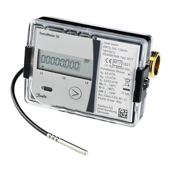
Danfoss SonoMeter 30 Installation Manual
Ultrasonic energy meter for heating and cooling applications
Hide thumbs
Also See for SonoMeter 30:
- Installation & user manual (13 pages) ,
- User manual (20 pages) ,
- User manual (4 pages)

Related Manuals for Danfoss SonoMeter 30


Summary of Contents for Danfoss SonoMeter 30
- Page 1 Installation guide SonoMeter 30 Ultrasonic energy meter for heating and cooling applications www.danfoss.com...
-
Page 2: Eu Declaration Of Conformity
Energy Metering Category Manager Danfoss only vouches for the correctness of the English version of this declaration. In the event of the declaration being translated into any other language, the translator concerned shall be liable for the correctness of the translation... -
Page 3: Installation
Calculator at max. 45° C. Avoid installation stress from pipes and fittings. Flush the system. 1.2. Identification of installation: Return/Supply pipe installation and flow direction Flow direction Return pipe installation Flow direction Supply pipe installation BC200586470576en-020601 © Danfoss | Energy Meters | 2020.11 | 3... -
Page 4: Mounting Of Flow Sensor
The possible ways of the mounting of the calculator (auxiliary holder): - Direct mounting on the housing of the flow sensor, by turning each 90o (only when the flow temperature does not exceed 90oC): 4 | © Danfoss | Energy Meters | 2020.11 BC200586470576en-020601... - Page 5 5°C. In this case, it is recommended to attach the calculator so that between it and wall surfaces there was an air gap not less than 5 cm. BC200586470576en-020601 © Danfoss | Energy Meters | 2020.11 | 5...
- Page 6 Installation recommendations for ball valve mounting and sealing direct short temperature sensors Seal Seal Pocket Pocket a) angled 45° b) perpendicular Installation recommendations for pocket temperature sensors with permanently connected signal leads. 6 | © Danfoss | Energy Meters | 2020.11 BC200586470576en-020601...
-
Page 7: Electrical Wiring
1: Additional pulse input V2 is on. 2: Additional pulse input V1 is on. T1: flow temperature sensor. T2: return temperature sensor. V1: additional pulse input/output 1. V2: additional pulse input/output 2. 7 | © Danfoss | Energy Meters | 2020.11 BC200586470576en-020601... -
Page 8: Terminals Description
12-24 V DC power supply voltage for Modbus and LON (bipolar) RS-485 Modbus RTU module (+) or BACnet (+) RS-485 Modbus RTU module (+) or BACnet (+) LON module (line A) LON module (line B) 8 | © Danfoss | Energy Meters | 2020.11 BC200586470576en-020601... - Page 9 IP65 for heat meter IP67 for heat and cooling meter Display function overview 4.1. Menu structure Integral parameters Long press 2.6.1 2.7.1 2.15.1 Statistical data Short press 3.6.1 3.15 Informative parameters 9 | © Danfoss | Energy Meters | 2020.11 BC200586470576en-020601...
-
Page 10: Display Symbols
Explanation of special symbols: flow is flowing forward (right direction) flow is flowing backwards (wrong direction) no arrow no flow Explanation of other symbols are described in detailed instruction on www.heating.danfoss.com. 4.3. Error codes Calculate errors Error codes may consist of up to 4 symbols. - Page 11 Other plastic parts PC, PPS, PEI, TPE Plastic recovery 6. Local Importer name and address For goods delivered to UK, importer name and address is: Danfoss Ltd. Oxford Road UB9 4LH Denham 11 | © Danfoss | Energy Meters | 2020.11 BC200586470576en-020601...
- Page 12 12 | © Danfoss | Energy Meters | 2020.11 BC200586470576en-020601...
Need help?
Do you have a question about the SonoMeter 30 and is the answer not in the manual?
Questions and answers