Table of Contents
Advertisement
Quick Links
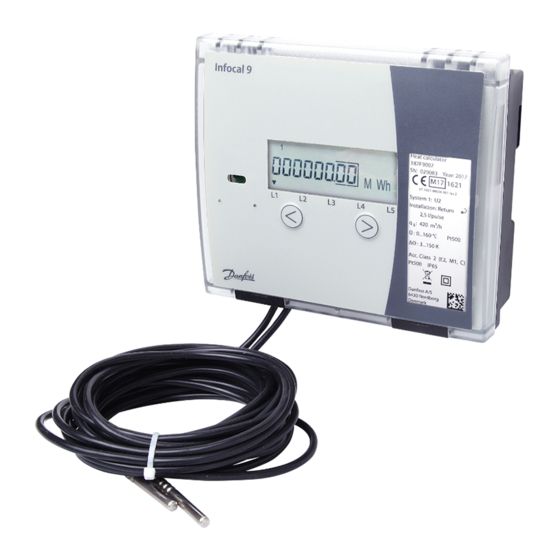
Installation & User Guide
Infocal 9
Energy calculator
for heating and cooling applications
www.danfoss.com
Advertisement
Table of Contents

Subscribe to Our Youtube Channel
Related Manuals for Danfoss Infocal 9


Summary of Contents for Danfoss Infocal 9
- Page 1 Installation & User Guide Infocal 9 Energy calculator for heating and cooling applications www.danfoss.com...
- Page 2 Installation & User Guide Infocal 9 2 | © Danfoss | Energy Meters | 2017.03 VUIGN102...
- Page 3 More detailed instructions can be found on www.heating.danfoss.com. 1.2. Identification of installation: Return or Supply pipe flow meter/sensor installation Flow direction Flow meter/sensor installed in return pipe Flow direction Flow meter/sensor installed in supply pipe VUIGN102 © Danfoss | Energy Meters | 2017.03 | 3...
- Page 4 Sensor marking sensor sensor position (5-6) (1/5-6/2) Supply pipe Heating or Heating/cooling Blue (7-8) (3/7-8/4) Return pipe Cold Cold 1.4. Mounting and sealing of calculator On standard DIN-rail: On the wall: 4 | © Danfoss | Energy Meters | 2017.03 VUIGN102...
- Page 5 1.5. Flow meter or flow sensor connection For connection of flow meter/sensor to energy calculator Infocal 9 it is important to know in which pipe (supply –q1 or return – q2) this flow meter/sensor will be installed: Flow sensor in supply pipe...
- Page 6 - pulse inputs from water meters T1 - temperature sensor in supply pipe T2 - temperature sensor in return pipe Note: Only required for selected calculator type should be connected 6 | © Danfoss | Energy Meters | 2017.03 VUIGN102...
- Page 7 Current terminal for 2-nd temperature sensor “+I” Voltage terminal for 2-nd temperature sensor “+U” Voltage terminal for 2-nd temperature sensor “-U” Current terminal for 2-nd temperature sensor “-I” Shield terminal (for 2-nd temperature sensor etc. ) VUIGN102 © Danfoss | Energy Meters | 2017.03 | 7...
- Page 8 1. Bleed the system until the flow rate display is steady. 2. Make sure no error codes are displayed. 3. Check the display for a plausible indication of flow rate and temperatures. 8 | © Danfoss | Energy Meters | 2017.03 VUIGN102...
- Page 9 Configuration settings parameters (L5) TEST Parametrization (configuration) mode (SET) TEST Test mode (TEST) Note: More detailed display description is available for download from www.danfoss.com. 4.3. Error codes check The calculator continuously analyzes operational modes, diagnoses and informs of errors in system. General errors:...
- Page 10 Status of sensor Θ2 Display Description Er2: 0 No error. Normal mode. Er2: 1 Temperature difference is under programmed minimum allowed value. Er2: 8 Sensor failure (open circuit or short circuit). 10 | © Danfoss | Energy Meters | 2017.03 VUIGN102...
- Page 11 Approved deposit for lithium Battery 3.5 g lithium batteries Coppered epoxy laminate components PCBA with display Electronic waste soldered on, PC, TPE Other plastic parts PC, PPS, PEI, TPE Plastic recovery VUIGN102 © Danfoss | Energy Meters | 2017.03 | 11...
- Page 12 • www.heating.danfoss.com Danfoss can accept no responsibility for possible errors in catalogues, brochures and other printed material. Danfoss reserves the right to alter its products without notice. This also applies to products already on order provided that such alterations can be made without subsequential changes being necessary in specifications already agreed.
Need help?
Do you have a question about the Infocal 9 and is the answer not in the manual?
Questions and answers