Table of Contents
Advertisement
Quick Links
DCF36 - LIGHT
19,000 BTU
Natural Gas & Propane
Installation and Operating Instructions
MODEL: DCF36 – LIGHT
IF THE INFORMATION IN THESE INSTRUCTIONS IS NOT FOLLOWED EXACTLY, A FIRE OR
EXPLOSION MAY RESULT CAUSING PROPERTY DAMAGE, PERSONAL INJURY, OR DEATH.
Do not store or use gasoline or other flammable vapors and liquids in the vicinity of this or
WHAT TO DO IF YOU SMELL GAS:
•
Do not try to light any appliance
•
Do not touch any electrical switch; do not use any phone in your building
Immediately call your gas supplier from a neighbour's phone. Follow gas supplier's
•
instructions
•
If you cannot reach your gas supplier, call the fire department.
Installation and service must be performed by a qualified installer, service agency or gas
supplier.
WARNING: Improper installation, adjustment, alteration, services or maintenance can cause
injury or property damage. Refer to this manual. For assistance or additional information
consult a qualified installer, service agency or the gas supplier.
PLEASE READ THIS MANUAL BEFORE
INSTALLING OR USING THIS APPLIANCE.
SAVE THIS MANUAL FOR FUTURE
REFERENCE.
A BARRIER DESIGNED TO REDUCE THE RISK OF
BURNS FROM THE HOT VIEWING GLASS IS
PROVIDED WITH THIS APPLIANCE AND MUST BE
INSTALLED.
INSTALLER: Leave this manual with the appliance.
CONSUMER: Retain this manual for future reference.
CLIENT # LC773211
WARNING
any other appliance.
Page 1 of 57
Advertisement
Table of Contents

Subscribe to Our Youtube Channel
Related Manuals for Inca Metal Cutting DCF36-LIGHT


Summary of Contents for Inca Metal Cutting DCF36-LIGHT
- Page 1 DCF36 - LIGHT 19,000 BTU Natural Gas & Propane Installation and Operating Instructions MODEL: DCF36 – LIGHT CLIENT # LC773211 WARNING IF THE INFORMATION IN THESE INSTRUCTIONS IS NOT FOLLOWED EXACTLY, A FIRE OR EXPLOSION MAY RESULT CAUSING PROPERTY DAMAGE, PERSONAL INJURY, OR DEATH. Do not store or use gasoline or other flammable vapors and liquids in the vicinity of this or any other appliance.
- Page 2 DCF36 - LIGHT 19,000 BTU GAZ NATUREL ET PROPANE Manuel D’installation et Guide de l’utilisateur MODEL: DCF36 - LIGHT CLIENT # LC773211 AVERTISSEMENT ASSUREZ-VOUS DE BIEN SUIVRE LES INSTRUCTIONS DONNÉES DANS CETTE NOTICE POUR RÉDUIRE AU MINIMUM LE RISQUE D'INCENDIE OU D'EXPLOSION OU POUR ÉVITER TOUT DOMMAGE MATÉRIEL, TOUTE BLESSURE OU LA MORT.
-
Page 3: Table Of Contents
Table of Contents IMPORTANT SAFETY INFORMATION …………………………………………………………….. 4 – 5 INTRODUCTION ........................Specifications, Appliance Dimensions & Installation Codes ......... 6 - 8 Features ........................8 Intended Use ......................8 General Safety ....................9 - 10 OPERATION ........................... Lighting Instructions ..................11 - 12 Heat Output Adjustment ................... -
Page 4: Important Safety Information
WARNING • Read this owner’s manual carefully and completely before trying to assemble, operate or service this fireplace. Follow instructions for proper installation • Failure to install this appliance per the manufacturer’s instructions or failure to use only parts specifically approved with this appliance may result in property damage or personal injury. - Page 5 WARNING AVERTISSEMENT Ne pas utiliser cet appareil s’il a été plongé, Do not use this appliance if any part has meme partiellement, dans l’eau. Appeler un been under water. Immediately call a technician qualifié pour inspecter l’appareil et qualified service technician to inspect the appliance and to replace any part of the remplacer toute partie du système de control system and any gas control which...
-
Page 6: Introduction
1.0 INTRODUCTION 1.1 SPECIFICATIONS TABLE 1 ITEM NATURAL GAS (NG) PROPANE (LP) MAXIMUM INPUT: Hi 19,000 Btu/hr (5.57 kW) 17,000 Btu/hr (4.98 kW) MINIMUM INPUT: Lo 12,000 Btu/hr (3.52 kW) 12,000 Btu/hr (3.52 kW) MANIFOLD PRESSURE: 3.5” w.c. (0.87 kPa) 10.0”... - Page 7 APPLIANCE DIMENSIONS CONVERTIBLE TOP VENT / REAR VENT Page 7 of 57...
-
Page 8: Features
INSTALLATION CODES This appliance is a Direct Vent appliance which draws all combustion air from outside the building through an intake vent pipe. Installation must conform to local codes. In the absence of local codes, installation must conform to the National Fuel Gas Code ANSI Z223.1/NFPA 54, or the current Natural Gas and Propane Installation Code CSA B149.1. -
Page 9: General Safety
1.4 GENERAL SAFETY / SÉCURITÉ GÉNÉRALE • Maintain adequate clearances around air openings into the combustion chamber. • Respecter les distances minimales convenables autour des bouches d'air dans la chambre de combustion. • Maintain adequate accessibility clearances for servicing and proper operation. •... - Page 10 IMPORTANT PLEASE READ THE FOLLOWING CAREFULLY It is normal for fireplaces fabricated of steel to give off some expansion and/or contraction noises during the start up or cool down cycle. It is not unusual for gas fireplaces to give off some odors the first time they are burned. This is due to the oils and sealants in the manufacturing process.
-
Page 11: Operation
2.0 OPERATION LIGHTING INSTRUCTIONS - for Intermittent Pilot FOR YOUR SAFETY, READ BEFORE LIGHTING WARNING: If you do not follow these instructions exactly, a fire or explosion may result causing property damage, personal injury or loss of life. This appliance is equipped with an ignition device which automatically lights the pilot. Do not try to light the pilot by hand. BEFORE LIGHTING smell all around the appliance area for gas. - Page 12 INSTRUCTIONS D'ALLUMAGE - Pilote intermittent POUR PLUS DE SÉCURITÉ, LIRE AVANT D’ALLUMER AVERTISSEMENT: Quiconque ne respecte pas à la letter les instructions dans la présente notice risqué de déclencher un incendie ou une explosion entraînant des dommages, des blessures ou la mort. Cet appareil est équipé...
-
Page 13: Heat Output Adjustment
2.2 HEAT OUTPUT ADJUSTMENT The valve supplied with the appliance has a HI/LO knob to control the heat output and flame height (see valve diagram in lighting instructions section 2.1) 2.3 BASIC FAN OPERATION For units equipped with a fan control knob, the knob is located in the valve control compartment and may be adjusted to the following settings: OFF: Turn the control fully counter-clockwise until the switch operates. -
Page 14: Installation
3.0 INSTALLATION 3.1 INSTALLATION & SAFETY NOTES / NOTES D'INSTALLATION ET DE SECURITE Read all instructions before starting installation and follow them carefully during installation to ensure maximum benefit and safety. Failure to follow these instructions will void your warranty and may present a fire hazard. -
Page 15: Minimum Clearances Requirements Top Vent
3.3.1 MINIMUM CLEARANCES TOP VENT / DÉGAGEMENT MINIMAL DE L’ÉVENT SUPÉRIEUR FRAMING DIMENSIONS 35.52" W x 36.74" H x 15" D MINIMUM CLEARANCES TO COMBUSTIBLES TOP VENT A = 50.5” TO INTERNAL CEILING B = 1” TO INTERNAL BACK COMBUSTIBLES C = 15”... -
Page 16: Minimum Clearances Requirements Rear Vent
3.3.1 MINIMUM CLEARANCES REAR VENT / DÉGAGEMENT MINIMAL ÉVENT ARRIÈRE FRAMING DIMENSIONS (SEE PAGE 7) 35.52" W x 37.44" H x 15" D MINIMUM CLEARANCES TO COMBUSTIBLES REAR VENT A = 41.00” TO INTERNAL CEILING B = 1” TO INTERNAL BACK COMBUSTIBLES C = 15”... - Page 17 The fireplaces have been tested to 140 degrees 12” out from the bottom front of the fireplace for flooring temperatures. When using any type of manufactured flooring you must confirm with the flooring manufacturer that these temperatures are allowable on the flooring you choose. The fireplace manufacturer is not responsible for any damage to flooring not installed accordingly.
-
Page 18: Gas Line Installation
Millivolt thermostats are available from any authorized Inca Metal Cutting dealer. Bedroom installations require the use of a wall thermostat. Note: Thermostats are not allowed in the United States. -
Page 19: Thermostat,Wall Switch Or Digital On/Off Remote
The thermostat, digital on/off remote or wall switch MUST be rated for millivolt use. Minimize splicing in all millivolt wiring & crimp all unavoidable splices. Le thermostat numérique, télécommande marche / arrêt ou l'interrupteur mural doit être évalué pour une utilisation en millivolts. Minimiser épissage dans l'ensemble du câblage millivolt &... -
Page 20: Direct Vent Information
TO WALL SWITCH OR THERMOSTAT TO IGNITOR GAS VALVE TO THERMOCOUPLE 3.3.4 DIRECT VENT INFORMATION / DIRECT VENT D'INFORMATION The unit must be connected to listed 2-ply aluminium venting and vent cap / termination kit, 4” flex vent on the exhaust side and listed 7”... - Page 21 Figure 5 This appliance’s venting system is room sealed or Direct Vent. This means that it does not require room air for combustion but draws air from outside the building. USE OF COUPLERS – WITH FLEX PIPE In the event of a puncture of the vent pipe or if an extension is needed couplers may be used. High temperature sealant shall be applied to the ends of the coupler and the coupler shall then be inserted into the flex vent.
- Page 22 Security Venting The minimum vent system for horizontal termination must consist of: Dura-Vent adapter Part # W175-0053 directly on top of unit 12” (305mm) vertical length of vent 90 degree elbow 12" (305 mm) horizontal length of vent Wall thimble part #IMC1082A Horizontal termination cap SV4CHC The maximum horizontal vent system consists of: Dura-Vent adapter Part # W175-0053 directly on top of unit...
- Page 23 ICC Venting The minimum vent system for horizontal termination must consist of: ICC adapter TM-A446 directly on top of unit 12” (305mm) vertical length of vent 90 degree elbow 12" (305 mm) length horizontally Wall thimble part # TM-4WT Horizontal termination cap TM-4HT The maximum horizontal vent system consists of: ICC adapter TM-A446 directly on top of unit 34' (10363 mm) vertical length directly on top of the stove...
- Page 24 VERTICAL VENT TABLE NOTE: All vent dimensions are measured from the appliance (All values are in feet) surface where the vent connects to the point where exhaust gases exit the termination. REMARQUE: Toutes les dimensions sont mesurées à partir d'aération de la surface de l'appareil où l'évent se connecte au point où...
- Page 25 REAR VENT 20” MAXIMUM MUST HAVE MINIMUM RISE 20” MAXIMUM WITH 45° BEND OFF BACK OF UNIT Page 25 of 57...
- Page 26 34’ 20’ 8” MINIMUM TO CENTER VENT 20” MAXIMUM (Example: Where A---A = Vertical @ 2’ B---B = Horizontal @ 5’) A minimum clearance to combustibles must be maintained around the vent pipe of 1” on all horizontal and vertical pipe runs Un dégagement minimum aux matériaux combustibles doit être maintenu autour du tuyau de 1 "sur toutes les canalisations horizontales et verticales fonctionne Page 26 of 57...
- Page 27 USE OF SEALANT Sealant is required on vent system joints, except Metal-Fab Sure-Seal direct vent system joints (figure 7). On longer vent runs, especially vertical runs, sealant will ensure that the combustion air enters from outdoors, and not through the vent joints. Use high temperature sealant, available from local suppliers, on the inner pipe joint, applying the sealant around the outside of the male part of the vent.
- Page 28 Alignment holes Attachment screws 3/. Fasten Restrictor Plate back in place. RESTRICTOR PLATE Page 28 of 57...
- Page 29 Typical Dura- Vent, Security Chimney & Metal-Fab Venting Installation: Vent terminals shall not be recessed into a wall or siding. Fireplace Horizontal Wall Vent Terminations The position of the horizontal vent termination must be positioned in such a way as to meet all local building codes.
- Page 30 Install the wall thimble, on the inside of the exterior wall, shield using wood screws. Attach the venting to the termination using sheet metal screws, for Z-Flex installations an Inca Metal Cutting’s termination part # IMC1070A or IMC1070B shall be used and when using Simpson Dura-Vent or Security Venting a Simpson Dura-Vent termination part # P574 shall be used.
- Page 31 TOUJOURS vérifier les codes locaux avant l'installation VENTILATION. ETC DÉGAGEMENTS, peut varier d'ÉTAT (PROVINCE). CONSULT DURAVENT PARTS LIST OR INCA METAL CUTTING’S FIREPLACE MANUFACTURING PARTS LIST FOR PART NUMBERS. FOYER Duravent CONSULT LISTE DES PIÈCES OU COUPE METAL INCA de fabrication LISTE DES PIÈCES DE RÉFÉRENCE.
- Page 32 Termination above Roof Consult local codes for minimum vent cap height above the roof (X), vent must be a minimum of 2’ from any wall. To prevent water seepage; install the flashing with upper portion under the roofing material and the lower portion over the roofing material.
- Page 33 In accordance with the current CSA B149.1, Natural Gas and Propane Installation Code In accordance with the current ANSI Z223.1 / NFPA 54, National Fuel Gas Code † A vent shall not terminate directly above a sidewalk or paved driveway that is located between two single family dwellings and serves both dwellings ‡...
-
Page 34: Ceramic Logs Installation
3.3.5 CERAMIC LOG INSTALLATION / INSTALLATION BÛCHES EN CÉRAMIQUE Burn medium positions are critical to the safe and clean operation of this appliance. Never add any other material into the firebox. Use only with burn medium supplied with this unit. Burn positions moyennes sont critiques pour le fonctionnement sûr et propre de cet appareil. - Page 35 Position Log #2 on the 2 pins on the left side of the firebox as shown below / Positionnez la bûche #2 sur les 2 broches sur le côté gauche de la chambre de combustion comme indiqué ci-dessous Position the 3 log on the 2 pins on the right hand side of the firebox as shown below / Positionnez la 3ème bûche sur les 2 broches sur le côté...
- Page 36 Position the 5 log on the left hand side of the firebox and with the long finger resting in the cutout on the left side of the back log as shown below / Placez la 5ème bûche sur le côté gauche de la chambre de combustion et avec le long doigt reposant dans la découpe sur le côté...
-
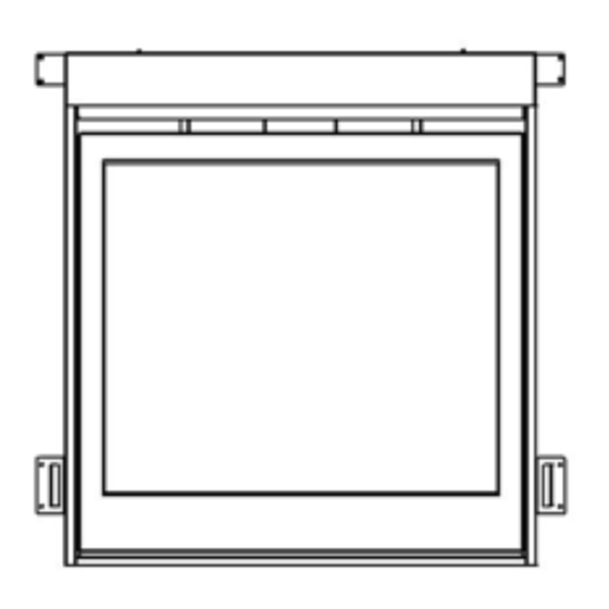
Page 37: Door Installation And Safety Screen
Install the door see instructions below. / Installez la porte voir les instructions ci-dessous. Turn your fireplace on and wait approximately 10-15 minutes until the flames are a nice yellow colour. Note the flame pattern and in any low or high areas adjust the amount of rockwool to correct gas flow. / Allumez votre foyer et attendez environ 10 à... - Page 38 Pull top door clips forwards and release to lock over the top door brackets / Tirez les clips de porte supérieurs vers l’avant et relâchez-les pour verrouiller les supports de porte supérieurs When closed properly the door latch will hook over the top of the door bracket and seal the door onto the fireplace. / Quand il est fermé...
-
Page 39: Initial Firing
3.3.6 SAFETY SCREEN / ÉCRAN DE SÉCURITÉ A mandatory safety screen is supplied with this appliance. It is secured to the door. / Un écran de sécurité obligatoire est fourni avec cet appareil. Il est fixé à la porte. 3.3.7 INITIAL FIRING When lit for the first few times, the appliance may emit an odor resulting from evaporation of paint and lubricants used in the manufacturing process. -
Page 40: Primary Air Adjustment
3.3.9 PRIMARY AIR ADJUSTMENT / AJUSTEMENT DE L'AIR PRIMAIRE Aeration is factory set but may need adjustment for altitude or movement during shipping. / L'aération est réglée en usine, mais peut nécessiter un ajustement de l'altitude ou le mouvement pendant le transport. To adjust the air shutter / Pour ajuster l'obturateur d'air 1/. -
Page 41: Fan Access
All valves have been pre-set and certified for installation at elevations from 0 – 4500 feet (0-1372m) above sea level. The appliance is certified to CSA 2.17- 2017 (R2022) – gas fired appliances for use at high altitudes. When installing this unit at higher elevations, it is necessary to decrease the input rating by replacing the existing burner orifice with a smaller size for installations over 4500 feet (1372m). -
Page 42: Gas Valve Access
3.3.12 GAS VALVE ACCESSIBILITY / ACCESSIBILITÉ ROBINET DE GAZ. TURN THE MAIN GAS & POWER OFF TO FIREPLACE BEFORE COMMENCING ANY WORK ON THE FIREPLACE THIS SHOULD BE DONE BY A LICENSED, CERTIFIED GAS INSTALLER TURN LE PRINCIPAL GAZ ET MISE HORS TENSION AU FOYER AVANT DE COMMENCER TOUT TRAVAIL SUR LA FOYER CELA DEVRAIT ETRE FAIT PAR UNE LICENCE, VOTRE FOURNISSEUR DE GAZ 1/. -
Page 43: Recommended Service
4.2 RECOMMENDED SERVICE / SERVICE RECOMMANDÉ 1. The venting system should be annually inspected by a qualified agency. / Le système de ventilation devrait être inspectés annuellement par une agence qualifiée. 2. Visually check the burner and pilot flames occasionally. Visually inspect height and color of flames / Contrôler visuellement le brûleur et les flammes pilotes à... -
Page 44: Valve & Pilot Replacement
VALVE PILOT ASSEMBLY REPLACEMENT SOUPAPE REMPLACEMENT ENSEMBLE PILOTE WARNING AVERTISSEMENT THE FOLLOWING PROCEDURE IS TO BE PERFORMED BY QUALIFIED PERSONNEL ONLY TURN OFF THE GAS TO THE MAIN BURNER AND ALLOW THE HEATER TO COOL FOR UP TO 30 MINUTES BEFORE SERVICING. LA PROCÉDURE SUIVANTE EST EFFECTUER PAR DU PERSONNEL QUALIFIÉ... - Page 45 2. Air in gas lines 2. Purge gas lines 3. Gas lines may not be connected 3. Connect all gas lines 4. Low pressure may be caused 4. Check for a kinked line by bent line A. Thermocouple / Valve II.
-
Page 46: Replacement Parts
6.0 REPLACEMENT PARTS When requesting service or replacement parts for your unit, please provide model name and serial number. All parts listed below may be ordered from an authorized dealer. Description Part# Certification Door 2145 Burner 2134 GL43X188 CSA / UL Door Glass 2155 ASTM C1048... -
Page 47: Warranty
INCA METAL CUTTING’S LIMITED LIFETIME GAS FIREPLACE WARRANTY Your Inca Metal Cutting gas fireplace is guaranteed to be free of defects in materials and workmanship for the lifetime of the fireplace. This limited lifetime guarantee covers: fireplace inner & outer shells, combustion chambers, heat exchangers and stainless steel parts against tarnishing. - Page 48 Inca Metal Cutting neither assumes, nor authorizes any third party to assume, on its behalf, any other liabilities with respect to the sale of this product. Inca Metal Cutting will not be responsible for: over firing, downdrafts, spillage caused by environmental conditions such as rooftops, buildings, nearby trees, hills, mountains, inadequate vents, excessive venting configurations, insufficient make up air, or negative air pressures which may or may not be caused by mechanical systems such as exhaust fans, furnaces, clothes dryers, etc.
- Page 49 à des dommages indirects, accessoires ou indirects. Cette garantie définit les obligations et la responsabilité de l'Inca Metal Cutting à l'égard de l'Inca Metal Cutting foyer au gaz et toute autre garantie expresse ou implicite à l'égard de ce produit, ses composants ou accessoires est exclue.
-
Page 50: Label Information
Inca Metal Cutting se réserve le droit d'avoir son représentant d'inspecter tout produit ou pièce avant d'honorer toute réclamation. 8.0 LABEL INFORMATION Page 50 of 57... - Page 51 8.0 LABEL INFORMATION (continued) WARNING Electrical Grounding Instructions This appliance is equipped with a three prong (grounding) plug for your protection against shock hazard and should be plugged directly into a properly grounded three prong receptacle. Do not cut or remove the grounding prong from this plug.
-
Page 52: Appendix A (Intermittent Pilot & Valve Kit)
APPENDIX A (AMERICAN FLAME VALVE INFORMATION) Page 52 of 57... - Page 53 APPENDIX A (Continued) Page 53 of 57...
- Page 54 APPENDIX A (Continued) Special Features on the AF-4000 System The AF-4000 Module can be powered two different ways. The first is a standard 110 volt AC to 6.0 volt DC adaptor. This adapter is connected to the AF-4000 Module by connecting the two 1/4” female terminals from the adapter to the two 1/4”...
-
Page 55: Appendix B (Conversion Kits & Label)
APPENDIX A (Continued) AF-4000 Wiring Diagram APPENDIX B (NG – LP CONVERSION KITS) This kit will convert the fireplace to Natural Gas / Propane (as applicable). / Ce kit vous permet de convertir la cheminée au gaz naturel / propane (le cas échéant). The Elite models are designed to burn either natural gas or propane. - Page 56 Conversion Kit Contents / Contenu du kit de conversion This conversion kit contains the following parts: Ce kit de conversion contient les éléments suivants: 1) Pilot orifice / orifice de la veilleuse 2) Burner orifice / orifice du brûleur 3) Fuel conversion label The proper steps for converting the appliance are as follows: / Les mesures adéquates pour convertir l'appareil sont les suivantes: 1) CAUTION: The gas supply shall be shut off prior to disconnecting the electrical power, before...
- Page 57 / technicien qui accepte la responsabilité que la conversion a été dûment remplie selon les instructions contenues dans ce manuel. Inca Metal Cutting Ltd Unit 100 – 11091 Bridgeport Road Richmond, BC V6X 1T3...
Need help?
Do you have a question about the DCF36-LIGHT and is the answer not in the manual?
Questions and answers