Table of Contents
Advertisement
TASMAN DV LINEAR FIREPLACE
26,000 BTU
Natural Gas
Installation and Operating Instructions
MODEL: ESSENCE
IF THE INFORMATION IN THESE INSTRUCTIONS IS
NOT FOLLOWED EXACTLY, A FIRE OR EXPLOSION
MAY RESULT CAUSING PROPERTY DAMAGE,
PERSONAL INJURY, OR DEATH.
Do not store or use gasoline or other flammable
vapors and liquids in the vicinity of this or any other
WHAT TO DO IF YOU SMELL GAS:
Do not try to light any appliance
Do not touch any electrical switch; do not use
any phone in your building
Immediately call your gas supplier from a
neighbour s phone. Follow gas supplier s
instructions
If you cannot reach your gas supplier, call the
fire department.
Installation and service must be performed by a
qualified installer, service agency or gas
supplier.
WARNING: Improper installation, adjustment,
alteration, services or maintenance can cause injury
or property damage. Refer to this manual. For
assistance or additional information consult a
qualified installer, service agency or the gas
supplier.
PLEASE READ THIS MANUAL BEFORE INSTALLING OR USING THIS APPLIANCE.
CERT # LC773211
WARNING
appliance.
SAVE THIS MANUAL FOR FUTURE REFERENCE.
D
UE TO HIGH TEMPERATURES
THE APPLIANCE SHOULD BE
LOCATED OUT OF TRAFFIC AND
AWAY FROM FURNITURE AND
DRAPERIES
C
HILDREN AND ADULTS SHOULD
BE ALERTED TO THE HAZARDS
OF HIGH SURFACE
TEMPERATURE AND SHOULD
STAY AWAY TO AVOID BURNS OR
CLOTHING IGNITION
Y
OUNG CHILDREN SHOULD BE
SUPERVISED WHEN THEY ARE IN
THE SAME ROOM AS THE
APPLIANCE
C
LOTHING OR OTHER
FLAMMABLE MATERIAL SHOULD
NOT BE PLACED ON OR NEAR THE
APPLIANCE
KEEP THE ROOM AREA CLEAR AND
FREE FROM COMBUSTIBLE
,
MATERIALS
GASOLINE
OTHER FLAMMABLE VAPORS AND
.
LIQUIDS
,
.
.
.
.
,
AND
Page 1 of 54
Advertisement
Table of Contents

Related Manuals for Inca Metal Cutting Tasman DV Linear ESSENCE


Summary of Contents for Inca Metal Cutting Tasman DV Linear ESSENCE
-
Page 1: Natural Gas
TASMAN DV LINEAR FIREPLACE 26,000 BTU Natural Gas Installation and Operating Instructions MODEL: ESSENCE CERT # LC773211 UE TO HIGH TEMPERATURES WARNING THE APPLIANCE SHOULD BE IF THE INFORMATION IN THESE INSTRUCTIONS IS LOCATED OUT OF TRAFFIC AND NOT FOLLOWED EXACTLY, A FIRE OR EXPLOSION AWAY FROM FURNITURE AND MAY RESULT CAUSING PROPERTY DAMAGE, DRAPERIES... - Page 2 DV TASMAN FOYER LINEAR AU GAZ NATUREL Manuel D installation et Guide de l utilisateur CERT # LC773211 N RAISON DE TEMPERATURES AVERTISSEMENT ELEVEES APPAREIL DOIT ETRE ASSUREZ-VOUS DE BIEN SUIVRE LES INSTRUCTIONS PLACE HORS DE LA CIRCULATION DONNÉES DANS CETTE NOTICE POUR RÉDUIRE AU ET LOIN DES MEUBLES ET MINIMUM LE RISQUE D'INCENDIE OU D'EXPLOSION OU TENTURES...
-
Page 3: Table Of Contents
Table of Contents IMPORTANT SAFETY INFORMATION .. 4 - 5 INTRODUCTION ........................Specifications, Appliance Dimensions & Installation Codes........6 - 7 Features, Remote Control Functions ..............8 - 10 Intended Use ......................11 General Safety....................11 - 12 OPERATION .......................... Lighting Instructions .................. -
Page 4: Important Safety Information
INSTALLER: Leave this manual with the INSTALLATEUR : Laissez cette notice avec appliance. l appareil. CONSUMER: Retain this manual for future CONSOMMATEUR : Conservez cette notice reference. pour consultation ultérieure. WARNING Read this owner s manual carefully and completely before trying to assemble, operate or service this fireplace. - Page 5 WARNING AVERTISSEMENT Do not use this appliance if any part has Ne pas utiliser cet appareil s il a été plongé, been under water. Immediately call a meme partiellement, dans l eau. Appeler un qualified service technician to inspect the technician qualifié...
-
Page 6: Introduction
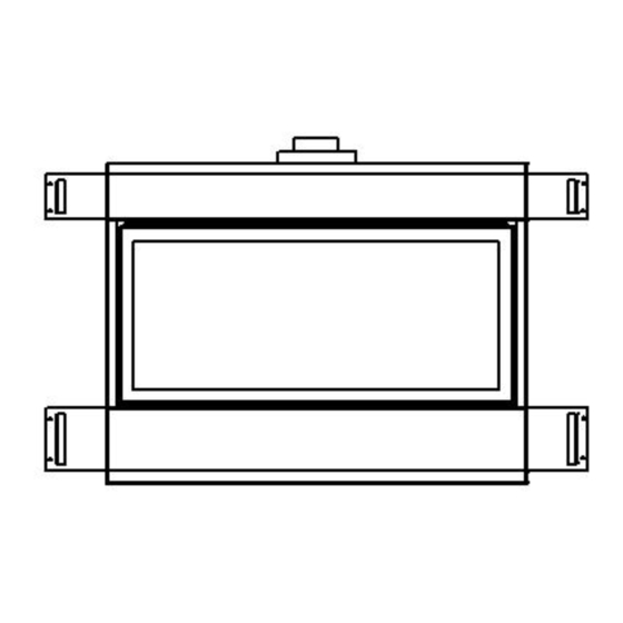
1.0 INTRODUCTION 1.1 SPECIFICATIONS TABLE 1 ITEM NATURAL GAS (NG) INPUT: Hi 26,000 Btu/hr (7.62 kW) INPUT: Lo 10,500 Btu/hr (3.07 kW) MANIFOLD PRESSURE: Hi 3.5 w.c. (0.87 kPa) COLLECTEUR DE PRESSION: FORT MANIFOLD PRESSURE: Lo 1.7 w.c. (0.42 kPa) COLLECTEUR DE PRESSION: FAIBLE GAS INLET SUPPLY PRESSURE: Minimum: 5.0 w.c. - Page 7 APPLIANCE DIMENSIONS Figure 1 19.022 37.935 10.045 19.446 COLLAR MUST BE 304 STAINLESS STEEL 3.992 MATERIAL, MINIMUM 33.625 24 GA THICKNESS 6.999 1.088 2.302 13.850 28.515 8.030 16.171 49.000 INSTALLATION CODES This appliance is a Direct Vent appliance which draws all combustion air from outside the building through an intake vent pipe.
-
Page 8: Features, Remote Control Functions
1.2 FEATURES Electronic Valve: Automatic DC valve with AC power adapter. Hand held remote control. Fan control Variable speed control: For units equipped with a fan control, adjust speed by remote control settings 1-6 Supreme Remote Control Functional Operation Matrix Initial Setup Installation of (2) AAA-size batteries will activate the setup mode. - Page 9 Press the UP or DOWN button to change the setting of P1 OFF. Press and release the SET button. Press the UP or DOWN button to change the setting of P2 ON. Press and release the SET button. Press the UP or DOWN button to change the setting of P2 OFF. Press and release the SET button. Press the UP or DOWN button to change the setting of the weekend (SS) P1 ON.
- Page 10 The fan will run for 12 minutes after the unit is shut off in any mode. The fan may not be controlled during this period. Continuous Pilot The unit can be changed from Intermittent Pilot Ignition (IPI), to Continuous, or standing, pilot. To place the unit in continuous pilot mode, press and release the PROG/TIME and the FLAME MAIN buttons simultaneously.
-
Page 11: Intended Use
1.3 INTENDED USE / USAGE PROPOSÉ This appliance is intended to be used as a zero clearance fireplace. Cet appareil est destiné à être utilisé comme un foyer à dégagement zéro. 1.4 GENERAL SAFETY / SÉCURITÉ GÉNÉRALE Maintain adequate clearances around air openings into the combustion chamber. Respecter les distances minimales convenables autour des bouches d'air dans la chambre de combustion. - Page 12 WARNING Hot while in operation. Do Not Touch. Severe burns may result. Keep children, clothing, furniture, gasoline and other liquids having flammable vapors away. Toddlers, young children and others may be susceptible to accidental contact burns. A physical barrier is recommended if there are at risk individuals in the house. To restrict access to a fireplace or stove install an adjustable safety gate to keep toddlers , young children and at risk individuals out of the room and away from hot surfaces.
-
Page 13: Operation
2.0 OPERATION LIGHTING INSTRUCTIONS - for Intermittent Pilot FOR YOUR SAFETY, READ BEFORE LIGHTING WARNING: If you do not follow these instructions exactly, a fire or explosion may result causing property damage, personal injury or loss of life. This appliance is equipped with an ignition device which automatically lights the pilot. Do not try to light the pilot by hand. BEFORE LIGHTING smell all around the appliance area for gas. - Page 14 INSTRUCTIONS D'ALLUMAGE - Pilote intermittent POUR PLUS DE SÉCURITÉ, LIRE AVANT D ALLUMER AVERTISSEMENT: Quiconque ne respecte pas à la letter les instructions dans la présente notice risqué de déclencher un incendie ou une explosion entraînant des dommages, des blessures ou la mort. Cet appareil est équipé...
-
Page 15: Installation
3.0 INSTALLATION 3.1 INSTALLATION & SAFETY NOTES / NOTES D'INSTALLATION ET DE SECURITE Read all instructions before starting installation and follow them carefully during installation to ensure maximum benefit and safety. Failure to follow these instructions will void your warranty and may present a fire hazard. -
Page 16: Minimum Clearances & Non Combustible Material Requirements
3.3.1 MINIMUM CLEARANCES / DÉGAGEMENTS 48.000 58.000 447.00 39.000 0.000 47.000 4.500 4.500 19.500 6.000 MINIMUM CLEARANCES TO COMBUSTIBLES A = 58 TO INTERNAL CEILING B = 4.5 TO INTERNAL SIDE COMBUSTIBLES C = 19.5 TO BACK WALL FROM FRONT OF UNIT D = 6 TO SIDE WALL E = 39... - Page 17 Mantle 42.000 12.000 Clearances are in accordance with local installation codes and the requirements of the gas supplier. **The mantel placement chart on this page illustrates the allowable mantel sizes and placements. The 45 degree angle can be used to determine the allowable mantel size based on the elevation above the units upper trim.
- Page 18 19.500 39.000 47.000 NOTE STUD MUST BE INSTALLED ON EDGE AS SHOWN IN THIS DIAGRAM The closest combustible material above the fireplace must be a minimum of 39 from the floor with the stud laying on edge as shown above. / Le plus proche matériau combustible au-dessus du foyer doit être un minimum de 39 "à...
- Page 19 NON COMBUSTIBLE MATERIAL/ MATIERE NON COMBUSTIBLES Heat Baffle fixed to non- combustible board by manufacturer (see next diagram for side view) Non Combustible material 12 (304.8mm) Non Combustible Non Combustible material 5.75 (146.05mm) material 5.75 (146.05mm) Non-combustible material will be supplied by the manufacturer. This must be installed around the fireplace as shown above to meet installation codes.
-
Page 20: Gas Line Installation
3.3.2 GAS LINE INSTALLATION / INSTALLATION DE LA LIGNE de GAZ Install supply line using any piping approved for your installation meeting CAN/CGA 6.10, AA 3, ANSI Z21.24 or Z21.45. A qualified gas fitter should install the gas line in accordance with all local building codes. If codes permit, coiled copper tubing may be used for gas supply. - Page 21 L'unité doit être raccordée à l'aluminium 2-plis énumérés ventilation, 4 "flex évent sur le côté de l'échappement et énumérés 7" flex évent sur le côté d'admission d'air ou peut être utilisé avec la sécurité d'évacuation ou de Simpson Dura-Vent 4 "x 5.6 / 8 "avec l'utilisation d'adaptateurs Simpson Dura-Vent partie # 's &...
- Page 22 Dura-Vent The minimum vent system for horizontal termination must consist of: Dura-Vent adapter Part # 0924N3 directly on top of unit 12 (300mm) vertical length of vent 90 degree elbow 12" (305 mm) length horizontally Wall thimble part #IMC1082A Horizontal termination cap 0984 The maximum horizontal vent system consists of: Dura-Vent adapter Part # 0924N3 directly on top of unit 34' (10363 mm) vertical length directly on top of the stove...
-
Page 23: Direct Vent Information
3.3.3 Direct Vent Information (continued) 2-Ply Aluminum Flex Vent The minimum vent system for horizontal termination must consist of: 12 (305 mm) vertical length (measured to center of vent pipe) with a 90 degree bend and a 12 (305 mm) horizontal length (measured from center of vent pipe) Wall thimble part# IMC1082A Horizontal termination cap part # IMC1070A or IMC1070B The maximum horizontal vent system consists of:... - Page 24 VENT TABLE (All values are in feet) 1 & 2 2 ½ 5 ½ 4 ½ 8 ½ 7 ½ 11 ½ 11 ½ 11 ½ 11 ½ 11 ½ 11 ½ V = 34 Feet Max. = 11 ½ Feet Max NOTE: All vent dimensions are measured from the appliance surface where the vent connects to the point where exhaust gases exit the termination.
- Page 25 12 Minimum 24 Maximum (Example: Where A---A = Vertical @ 2 ½ B---B = Horizontal @ 5 ) Page 25 of 54...
- Page 26 USE OF SEALANT Sealant is required on vent system joints (figure 7). On longer vent runs, especially vertical runs, sealant will ensure that the combustion air enters from outdoors, and not through the vent joints. Use high temperature sealant, available from local suppliers, on the inner pipe joint, applying the sealant around the outside of the male part of the vent.
- Page 27 VENT RESTRICTOR INSTALLATION (continued) The restrictors are installed by removing the 2 screws on the ceiling of the firebox, place the desired restrictor in place and use the screws to fasten the restrictor to the firebox. You must first remove the firebox baffle (4 screws) before installing the desired restrictor.
- Page 28 Install the wall thimble, on the inside of the exterior wall, shield using wood screws. Attach the venting to the termination using sheet metal screws, for Z-Flex installations an Inca Metal Cutting s termination part # IMC1070A or IMC1070B shall be used and when using Simpson Dura-Vent or Security Venting a Simpson Dura-Vent termination part # P574 shall be used.
- Page 29 TOUJOURS vérifier les codes locaux avant l'installation VENTILATION. ETC DÉGAGEMENTS, peut varier d'ÉTAT (PROVINCE). CONSULT DURAVENT PARTS LIST OR INCA METAL CUTTING S FIREPLACE MANUFACTURING PARTS LIST FOR PART NUMBERS. FOYER Duravent CONSULT LISTE DES PIÈCES OU COUPE METAL INCA de fabrication LISTE DES PIÈCES DE RÉFÉRENCE.
- Page 30 Termination above Roof Consult local codes for minimum vent cap height above the roof (X), vent must be a minimum of 2 from any wall. To prevent water seepage; install the flashing with upper portion under the roofing material and the lower portion over the roofing material.
- Page 31 In accordance with the current CSA B149.1, Natural Gas and Propane Installation Code In accordance with the current ANSI Z223.1 / 54, National Fuel Gas Code A vent shall not terminate directly above a sidewalk or paved driveway that is located between two single family dwellings and serves both dwellings Permitted only if veranda, porch, deck or...
-
Page 32: Rock & Glass Installation
3.3.4 Rock & Glass Installation / Rock & Installation de verre Burn medium positions are critical to the safe and clean operation of this appliance. Never add any other material into the firebox. Use only with burn medium supplied with this unit. Burn positions moyennes sont critiques pour le fonctionnement sûr et propre de cet appareil. -
Page 33: Door Installation
3.3.5 Door Installation Fit the top of the door onto the top door brackets, make sure the door is centered on the appliance. Push the bottom of the door into the appliance and pull the 2 door lock bars down, forward and up to secure the door in place. -
Page 34: Initial Firing
frame and with the rounded edge facing into the door place the glass panel back into the door frame. Then follow the instructions above to re-install the door. Si le verre a été endommagé ou cassé, il est fortement recommandé que vous contactez une personne qualifiée. -
Page 35: Primary Air Adjustment
PILOT FLAME ADJUSTMENT For proper operation, the pilot and main burner flames must be steady and not lifting off or floating. The top 3/8 1/2 (10-13mm) of the thermocouple should be engulfed by the pilot flame. 3.3.8 PRIMARY AIR ADJUSTMENT / AJUSTEMENT DE L'AIR PRIMAIRE Aeration is factory set but may need adjustment for altitude or movement during shipping. -
Page 36: Altitude Adjustment
6/. Reassemble the fireplace in reverse order from 4 through 2. / Remonter la cheminée dans l'ordre inverse de 4 à 2. 7/. Turn on the gas. / Allumez le gaz. PARTS REQUIRING ADJUSTMENT DURING OPERATION MAY BE HOT. CAUTION ATTENTION PIECES NECESSITANT REGLAGE PENDANT LA MARCHE PEUT ETRE CHAUDE Factory Setting... -
Page 37: Fan Access
3.3.10 FAN ACCESSIBILITY / FAN ACCESSIBILITÉ TURN THE MAIN GAS & POWER OFF TO FIREPLACE BEFORE COMMENCING ANY WORK ON THE FIREPLACE THIS SHOULD BE DONE BY A LICENSED, CERTIFIED GAS INSTALLER TURN LE PRINCIPAL GAZ ET MISE HORS TENSION AU FOYER AVANT DE COMMENCER TOUT TRAVAIL SUR LA FOYER CELA DEVRAIT ETRE FAIT PAR UNE LICENCE, VOTRE FOURNISSEUR DE 1/. - Page 38 4/. Remove the door clip / Retirez le clip de la porte 5/. Fans are attached with magnets for ease of installation and can be pulled off the rear wall. / Les fans sont attachés avec des aimants pour la facilité d'installation et peut être retiré de la paroi arrière Page 38 of 54...
- Page 39 6/. Once removed from the wall the fans will slide out through the opening. / Une fois retiré du mur que les fans vont glisser par l'ouverture. Note the fireplace has 2 fans one (1) on the left hand side and one (1) on the right hand side of the unit.
-
Page 40: Gas Valve Access
3.3.11 GAS VALVE ACCESSIBILITY / ACCESSIBILITÉ ROBINET DE GAZ. TURN THE MAIN GAS & POWER OFF TO FIREPLACE BEFORE COMMENCING ANY WORK ON THE FIREPLACE THIS SHOULD BE DONE BY A LICENSED, CERTIFIED GAS INSTALLER TURN LE PRINCIPAL GAZ ET MISE HORS TENSION AU FOYER AVANT DE COMMENCER TOUT TRAVAIL SUR LA FOYER CELA DEVRAIT ETRE FAIT PAR UNE LICENCE, VOTRE FOURNISSEUR DE GAZ 1/. -
Page 41: Maintenance
4.0 MAINTENANCE 4.1 MAINTENANCE SAFETY WARNING AVERTISSEMENT TURN OFF THE GAS TO THE MAIN BURNER AND ALLOW THE HEATER TO COOL FOR UP TO 30 MINUTES BEFORE SERVICING. COUPEZ LE GAZ AU BRÛLEUR PRINCIPAL ET LAISSEZ L'APPAREIL REFROIDIR PENDANT JUSQU'À 30 MINUTES AVANT L'ENTRETIEN. Service and repair should be done by a qualified service person. -
Page 42: Burner & Pilot Cleaning
4.4 BURNER & PILOT CLEANING Periodic cleaning is necessary for proper operation. Remove the burner, and check that the burner orifice is clean. Visually inspect the pilot. Brush or blow away any dust, lint, or foreign debris. If the pilot orifice is plugged, disassembly may be required to remove any foreign material from the orifice or tubing. -
Page 43: Trouble Shooting
5.0 TROUBLE SHOOTING SYMPTOM CORRECTIVE ACTION POSSIBLE CAUSE A. No spark at electrode (weak or not heat source for pilot ignition) Pilot will not light after repeated triggering of the remote control intermittent pilot 1. Improper ignition 1. Align the electrode with 1/8 (3mm) gap to pilot hood 2. - Page 44 4. Defective wiring 4. Conduct a test with a jumper wire and connections repair as required 5. Defective Valve 5. Contact service technician Soot deposits 1. Air inlet blocked or restricted 1. Clean air inlets 2. Vent system is restricted or 2.
-
Page 45: Replacement Parts
6.0 REPLACEMENT PARTS When requesting service or replacement parts for your unit, please provide model name and serial number. All parts listed below may be ordered from an authorized dealer. Description Part# Door IMC121 Burner IMC113 IMC001 Door Glass IMC002 Restrictor IMC127 Door Glass Gasket... -
Page 46: Warranty
INCA METAL CUTTING S GAS FIREPLACE S WARRANTY Your Inca Metal Cutting gas fireplace is guaranteed to be free of defects in materials and workmanship for a period of 5 years from the date of purchase. This covers: combustion chambers, heat exchangers and burners as well as stainless steel parts against tarnishing. - Page 47 Inca Metal Cutting neither assumes, nor authorizes any third party to assume, on its behalf, any other liabilities with respect to the sale of this product. Inca Metal Cutting will not be responsible for: over firing, downdrafts, spillage caused by environmental conditions such as rooftops, buildings, nearby trees, hills, mountains, inadequate vents, excessive venting configurations, insufficient make up air, or negative air pressures which may or may not be caused by mechanical systems such as exhaust fans, furnaces, clothes dryers, etc.
- Page 48 à des dommages indirects, accessoires ou indirects. Cette garantie définit les obligations et la responsabilité de l'Inca Metal Cutting à l'égard de l'Inca Metal Cutting foyer au gaz et toute autre garantie expresse ou implicite à l'égard de ce produit, ses composants ou accessoires est exclue.
-
Page 49: Label Information
8.0 LABEL INFORMATION Page 49 of 54... -
Page 50: Label Information
8.0 LABEL INFORMATION (continued) Sections of the venting system have not been installed. WARNING Do not operate the appliance until all sections have been assembled and installed in accordance with the manufacturer s instructions. Des sections du système d évacuation n ont pas été installées. AVERTISSEMENT - Ne pas utiliser l appareil tant que toutes les sections n ont pas été... -
Page 51: Appendix A (Intermittent Pilot & Valve Kit)
APPENDIX A (AMERICAN FLAME VALVE INFORMATION) Page 51 of 54... - Page 52 APPENDIX A (Continued) Page 52 of 54...
- Page 53 APPENDIX A (Continued) Special Features on the AF-4000 System The AF-4000 Module can be powered two different ways. The first is a standard 110 volt AC to 6.0 volt DC adaptor. This adapter is connected to the AF-4000 Module by connecting the two 1/4 female terminals from the adapter to the two 1/4 male terminals, located on the AF-4000 Module , marked POWER.
- Page 54 APPENDIX A (Continued) AF-4000 Wiring Diagram Inca Metal Cutting Unit 100 11091 Bridgeport Road Richmond, BC V6X 1T3 Canada Page 54 of 54...
Need help?
Do you have a question about the Tasman DV Linear ESSENCE and is the answer not in the manual?
Questions and answers