Table of Contents
Advertisement
Quick Links
Evaluating the ADMV8502 90 MHz to 225 MHz, Digitally Tunable, Band-Pass Filter
FEATURES
Fully featured evaluation board for the
►
On-board system demonstration platform (SDP-S) connector for
►
the SPI
Evaluation using on-board LDO regulators powered by the USB
►
ACE
software interface for SPI control
►
EQUIPMENT NEEDED
Network analyzer
►
®
Windows
PC
►
USB cable
►
EVAL-SDP-CS1Z (SDP-S) controller board
►
DOCUMENTS NEEDED
ADMV8502 data sheet
►
SOFTWARE NEEDED
ACE software
►
GENERAL DESCRIPTION
The ADMV8502-EVALZ is available for evaluating the ADMV8502
digitally tunable, band-pass filter (BPF). The ADMV8502-EVALZ
incorporates the ADMV8502 chip, as well as a negative voltage
generator, low dropout (LDO) regulators, and an interface to the
EVAL-SDP-CS1Z (SDP-S) system demonstration platform (SDP) to
allow simple and efficient evaluation. The negative voltage genera-
tor and LDO regulators allow the ADMV8502 to be powered by
either the 5 V USB supply voltage from the PC via the SDP-S or by
using two external power supplies.
The ADMV8502 is an IC that features a digitally selectable frequen-
cy of operation. The chip can be programmed using a 4-wire serial
peripheral interface (SPI), and the SDP-S controller allows the user
to interface with the SPI of the ADMV8502 through the Analog
Devices, Inc.,
Analysis, Control Evaluation
For full details on the ADMV8502, see the ADMV8502 data sheet,
which must be consulted in conjunction with this user guide when
using the ADMV8502-EVALZ.
PLEASE SEE THE LAST PAGE FOR AN IMPORTANT
WARNING AND LEGAL TERMS AND CONDITIONS.
ADMV8502
(ACE) software.
User Guide | EVAL-ADMV8502
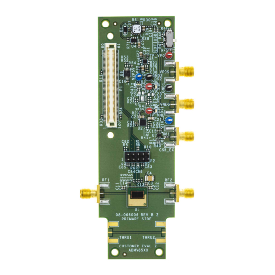
EVALUATION BOARD PHOTOGRAPH
Figure 1. ADMV8502-EVALZ Evaluation Board Photograph
UG-2196
Rev. 0 | 1 of 17
Advertisement
Table of Contents

Related Manuals for Analog Devices EVAL-ADMV8502


Summary of Contents for Analog Devices EVAL-ADMV8502
-
Page 1: Features
User Guide | EVAL-ADMV8502 UG-2196 Evaluating the ADMV8502 90 MHz to 225 MHz, Digitally Tunable, Band-Pass Filter FEATURES EVALUATION BOARD PHOTOGRAPH Fully featured evaluation board for the ADMV8502 ► On-board system demonstration platform (SDP-S) connector for ► the SPI Evaluation using on-board LDO regulators powered by the USB ►... -
Page 2: Table Of Contents
User Guide EVAL-ADMV8502 TABLE OF CONTENTS Features..............1 ADMV8502-EVALZ Quick Start......10 Equipment Needed..........1 Network Analyzer Settings....... 10 Documents Needed..........1 CSV Files............10 Software Needed...........1 Automatic Chip Reset........11 General Description..........1 Manual Chip Reset........... 11 Evaluation Board Photograph........1 Loss of Board Communication......11 Evaluation Board Hardware........3... -
Page 3: Evaluation Board Hardware
User Guide EVAL-ADMV8502 EVALUATION BOARD HARDWARE The ADMV8502-EVALZ has the ADMV8502 chip on board. The the VPOS and VNEG Subminiature Version A (SMA) ports or test ADMV8502-EVALZ also includes a negative voltage generator and points. The applicable voltage range for the positive input VPOS is three LDO regulators to provide the necessary supply voltages for between 3.5 V and 5.5 V, and the applicable voltage range for the... -
Page 4: Evaluation Board Software
User Guide EVAL-ADMV8502 EVALUATION BOARD SOFTWARE INSTALLING THE ACE SOFTWARE, ADMV8502 PLUG-INS, AND DRIVERS The ADMV8502-EVALZ uses the Analog Devices Analysis|Con- trol|Evaluation (ACE) software. For instructions on how to install and use the ACE software, go to www.analog.com/ACE. If the ACE software is already installed on the PC, ensure that the installed ACE software is the latest version, as listed on the ACE software page. -
Page 5: Plug-In Overview
User Guide EVAL-ADMV8502 EVALUATION BOARD SOFTWARE PLUG-IN OVERVIEW When the ADMV8502-EVALZ is connected to the PC, the ADMV8502 Board appears in the Attached Hardware section of the Start tab. Double-click the ADMV8502 Board plug-in to open two tabs, which are the ADMV8502 Board plug-in view (see... -
Page 6: Plug-In Details
User Guide EVAL-ADMV8502 EVALUATION BOARD SOFTWARE describes the functionality of each section. For additional detailed PLUG-IN DETAILS programming, refer to the ADMV8502 data sheet. The full screen ADMV8502 chip plug-in with labels is shown in Figure 7. The labels correspond to items listed in... - Page 7 User Guide EVAL-ADMV8502 EVALUATION BOARD SOFTWARE Table 1. ADMV8502 Chip Plug-In Label Functions (See Figure 7) (Continued) Label Function The Status section includes the following: Mode: when the SFL pin is low, the mode is SPI Write. When the SFL pin is high, the mode is SPI Fast Latch, and the chip uses the lookup table (LUT).
- Page 8 User Guide EVAL-ADMV8502 EVALUATION BOARD SOFTWARE Figure 8. ADMV8502 Memory Map in the ACE Software Figure 9. Interpolation Coefficients Subdiagram in the ACE Software analog.com Rev. 0 | 8 of 17...
- Page 9 User Guide EVAL-ADMV8502 EVALUATION BOARD SOFTWARE Figure 10. Coefficient Calibration Subdiagram in the ACE Software analog.com Rev. 0 | 9 of 17...
-
Page 10: Performing Evaluation
User Guide EVAL-ADMV8502 PERFORMING EVALUATION ADMV8502-EVALZ QUICK START CSV FILES To set up the ADMV8502-EVALZ, take the following steps: By default, the ADMV8502_Coefficients_Bandwidth_Nomi- nal.csv file is loaded into the CONFIGURATION section. This file 1. Connect the RF1 and RF2 ports to a network analyzer (or a contains interpolation coefficients that correspond to approximately similar instrument). -
Page 11: Automatic Chip Reset
User Guide EVAL-ADMV8502 PERFORMING EVALUATION AUTOMATIC CHIP RESET REGULATOR BYPASS If a reset of the ADMV8502 chip is required on the ADMV8502- The ADMV8502-EVALZ has a negative voltage generator and three EVALZ, click Reset Chip (see Figure 7, Label J3, and... -
Page 12: Evaluation Board Schematics And Artwork
User Guide EVAL-ADMV8502 EVALUATION BOARD SCHEMATICS AND ARTWORK ADMV8502-EVALZ Figure 12. ADMV8502-EVALZ Schematic, Page 1 analog.com Rev. 0 | 12 of 17... - Page 13 User Guide EVAL-ADMV8502 EVALUATION BOARD SCHEMATICS AND ARTWORK Figure 13. ADMV8502-EVALZ Schematic, Page 2 analog.com Rev. 0 | 13 of 17...
- Page 14 User Guide EVAL-ADMV8502 EVALUATION BOARD SCHEMATICS AND ARTWORK Figure 14. ADMV8502-EVALZ Layer 1 Figure 15. ADMV8502-EVALZ Layer 2 analog.com Rev. 0 | 14 of 17...
- Page 15 User Guide EVAL-ADMV8502 EVALUATION BOARD SCHEMATICS AND ARTWORK Figure 16. ADMV8502-EVALZ Layer 3 Figure 17. ADMV8502-EVALZ Layer 4 analog.com Rev. 0 | 15 of 17...
-
Page 16: Ordering Information
User Guide EVAL-ADMV8502 ORDERING INFORMATION BILL OF MATERIALS Table 2. ADMV8502-EVALZ Quantity Reference Designator Description Manufacturer Part Number 2P5V, 3P3V, TP_VPO Test points, red Components Corporation TP-104-01-02 GND1, GND2 Test points, black Components Corporation TP-104-01-00 N2P5V, TP_VNE Test points, blue... - Page 17 Evaluation Board until you have read and agreed to the Agreement. Your use of the Evaluation Board shall signify your acceptance of the Agreement. This Agreement is made by and between you (“Customer”) and Analog Devices, Inc. (“ADI”), with its principal place of business at Subject to the terms and conditions of the Agreement, ADI hereby grants to Customer a free, limited, personal, temporary, non-exclusive, non-sublicensable, non-transferable license to use the Evaluation Board FOR EVALUATION PURPOSES ONLY.
Need help?
Do you have a question about the EVAL-ADMV8502 and is the answer not in the manual?
Questions and answers