Table of Contents
Advertisement
Quick Links
Evaluating the ADMV4630 14.0 GHz to 14.5 GHz, SATCOM, Ku-Band Upconverter
FEATURES
Fully featured evaluation board for the ADMV4630
►
On-board
SDP-S
connector for SPI control
►
Simplified power-up with on-board LDO regulators
►
5 V operation
►
ACE
software interface for SPI control
►
EVALUATION KIT CONTENTS
EVAL-ADMV4630Z evaluation board
►
Mini USB to USB cable
►
SDP-S
controller board
►
EQUIPMENT NEEDED
5 V dc power supply
►
DC clips
►
RF signal generator
►
Spectrum analyzer
►
Power supply cables, 2.92 mm coaxial cables
►
PC for
ACE
software
►
DOCUMENTS NEEDED
ADMV4630 data sheet
►
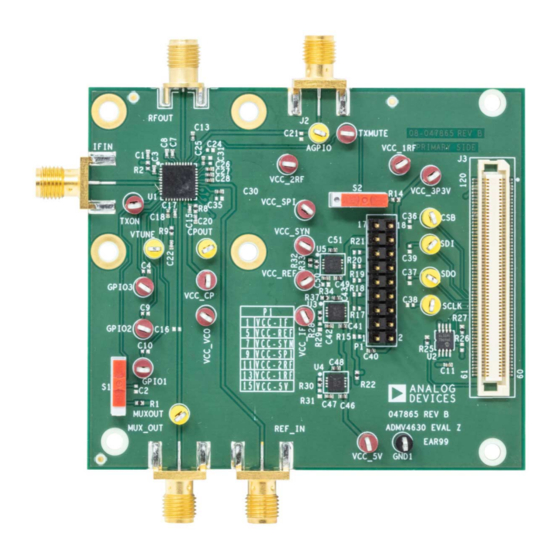
EVALUATION BOARD PHOTOGRAPH
PLEASE SEE THE LAST PAGE FOR AN IMPORTANT
WARNING AND LEGAL TERMS AND CONDITIONS.
User Guide | EVAL-ADMV4630
SOFTWARE NEEDED
ACE
software
►
ADMV4630 plugins
►
GENERAL DESCRIPTION
The evaluation board incorporates the ADMV4630, low dropout
(LDO) regulators, and the
board to allow simplified, efficient evaluation of the ADMV4630. The
SDP-S
controller board allows the configuration of the ADMV4630
register map through the
ware. The LDO regulators allow the EVAL-ADMV4630Z to be pow-
ered by a 5 V single supply.
The ADMV4630 is a Ku-band upconverter optimized for various
satellite communication (SATCOM) user terminals operating in the
14.0 GHz to 14.5 GHz frequency range. The ADMV4630 upconvert-
er comes in a compact, thermally enhanced, 6 mm × 6 mm, 40-lead
frame chip scale package (LFCSP). The ADMV4630 operates over
the −40°C to +85°C case temperature range.
For full details on the ADMV4630, see the
which must be consulted in conjunction with this user guide when
using the EVAL-ADMV4630Z.
Figure 1.
UG-1642
EVAL-SDP-CS1Z
(SDP-S) controller
Analysis, Control, Evaluation
ADMV4630
Rev. A | 1 of 11
(ACE) soft-
data sheet,
Advertisement
Table of Contents

Subscribe to Our Youtube Channel
Related Manuals for Analog Devices EVAL-ADMV4630


Summary of Contents for Analog Devices EVAL-ADMV4630
-
Page 1: Features
User Guide | EVAL-ADMV4630 UG-1642 Evaluating the ADMV4630 14.0 GHz to 14.5 GHz, SATCOM, Ku-Band Upconverter FEATURES SOFTWARE NEEDED Fully featured evaluation board for the ADMV4630 software ► ► On-board SDP-S connector for SPI control ADMV4630 plugins ► ► Simplified power-up with on-board LDO regulators ►... -
Page 2: Table Of Contents
User Guide EVAL-ADMV4630 TABLE OF CONTENTS Features..............1 Installing the ACE Software and ADMV4630 Evaluation Kit Contents......... 1 Plugins and Drivers.......... 4 Equipment Needed..........1 Configuring the Board........4 Documents Needed..........1 ADMV4630 Block Diagram and Functions.... 6 Software Needed...........1 Evaluation Board Schematics........8 General Description..........1... -
Page 3: Evaluation Board Hardware
User Guide EVAL-ADMV4630 EVALUATION BOARD HARDWARE The EVAL-ADMV4630Z comes with an on-board ADMV4630 chip. Figure 2 shows the block diagram of the EVAL-ADMV4630Z lab When evaluating the ADMV4630 device, connect the IF input to bench setup. an RF signal generator. The EVAL-ADMV4630Z runs on a 5 V dc supply. -
Page 4: Evaluation Board Software Quick Start Procedures
EVALUATION BOARD SOFTWARE QUICK START PROCEDURES INSTALLING THE ACE SOFTWARE AND ADMV4630 PLUGINS AND DRIVERS The EVAL-ADMV4630Z software uses the Analog Devices, Inc., software. Ensure that the software is installed before setting up or using the EVAL-ADMV4630Z. For instructions on how to install and use the software, go to www.analog.com/ACE. - Page 5 User Guide EVAL-ADMV4630 EVALUATION BOARD SOFTWARE QUICK START PROCEDURES 7. Click the Initialization & Optimization button in the ADMV4630 block diagram to initialize the device before opera- tion. Figure 6. ADMV4630 Block Diagram in the ACE Software 8. To set up the RF, use the following settings and measure the...
-
Page 6: Admv4630 Block Diagram And Functions
User Guide EVAL-ADMV4630 ADMV4630 BLOCK DIAGRAM AND FUNCTIONS ADMV4630 block diagram user interface with labels is shown in Figure 7, and Table 1 describes the functionality of each block. Figure 7. ADMV4630 Block Diagram with Labels Table 1. ADMV4630 Block Diagram Label Functions (See... - Page 7 User Guide EVAL-ADMV4630 ADMV4630 BLOCK DIAGRAM AND FUNCTIONS Table 1. ADMV4630 Block Diagram Label Functions (See Figure Label Function Click the AGPIO switch (represented by Label H) to set the SEL_AGPIO bit (Bit 3, Register 0x301). When the AGPIO switch is set to the right, the SEL_AGPIO bit is disabled and the AGPIO pin is used as data output.
-
Page 8: Evaluation Board Schematics
User Guide EVAL-ADMV4630 EVALUATION BOARD SCHEMATICS Figure 9. EVAL-ADMV4630Z Schematic, Page 1 analog.com Rev. A | 8 of 11... - Page 9 User Guide EVAL-ADMV4630 EVALUATION BOARD SCHEMATICS Figure 10. EVAL-ADMV4630Z Schematic, Page 2 analog.com Rev. A | 9 of 11...
-
Page 10: Ordering Information
User Guide EVAL-ADMV4630 ORDERING INFORMATION BILL OF MATERIALS Table 2. Reference Designators Description Manufacturer Part Number AGPIO, CPOUT, CSB, MUXOUT, SCLK, SDI, Test points, yellow Components Corporation TP-104-01-04 SDO, VTUNE C1, C5, C6, C20, C22, C32 to C34 1000 pF ceramic capacitors... -
Page 11: Notes
Evaluation Board until you have read and agreed to the Agreement. Your use of the Evaluation Board shall signify your acceptance of the Agreement. This Agreement is made by and between you (“Customer”) and Analog Devices, Inc. (“ADI”), with its principal place of business at Subject to the terms and conditions of the Agreement, ADI hereby grants to Customer a free, limited, personal, temporary, non-exclusive, non-sublicensable, non-transferable license to use the Evaluation Board FOR EVALUATION PURPOSES ONLY.
Need help?
Do you have a question about the EVAL-ADMV4630 and is the answer not in the manual?
Questions and answers