Table of Contents
Advertisement
Quick Links
One Technology Way • P.O. Box 9106 • Norwood, MA 02062-9106, U.S.A. • Tel: 781.329.4700 • Fax: 781.461.3113 • www.analog.com
Evaluating the 5.7 kV RMS
FEATURES
Simplified evaluation of the 25 Mbps
RS-485 transceiver
2-layer PCB compliant to EN 55032 Class B radiated emissions
Footprint for 10.15 mm × 10.05 mm, 28-lead SOIC_W_FP
package with >8.0 mm creepage and clearance
On-board
ADP7104
LDO regulator with jumper options for
simplified evaluation in 5 V or 3.3 V configuration
Flexible, low voltage V
supply rail to interface with I/O
IO
nodes as low as 1.7 V
Selectable 3.3 V or 5 V isolated supply voltage options available
IEC 61000-4-2 ESD protection on the A, B, Y, and Z pins
±12 kV contact discharge and ±15 kV air discharge
SMA connector for high speed 25 Mbps TxD input signal
Optional on-board
LTC6900
input signal
Screw terminal blocks for power connections, digital signals,
and RS-485 signals
Jumper-selectable enable and disable for digital input signals
Resistors and footprints for termination and loopback test
Test points to measure all signals
EVALUATION KIT CONTENTS
EVAL-ADM2867EEBZ
EQUIPMENT NEEDED
Oscilloscope
Signal generator
3.0 V to 5.5 V supply
1.62 V to 5.5 V supply
DOCUMENTS NEEDED
ADM2867E
data sheet
PLEASE SEE THE LAST PAGE FOR AN IMPORTANT
WARNING AND LEGAL TERMS AND CONDITIONS.
RS-485 Transceiver with ±15 kV IEC ESD
ADM2867E
oscillator to provide TxD
EVAL-ADM2867EEBZ
ADM2867E
Signal and Power Isolated
GENERAL DESCRIPTION
The EVAL-ADM2867EEBZ allows the simplified, efficient
evaluation of the 5.7 kV rms
isolated RS-485 transceiver.
The
ADM2867E
that provides power to the isolated side of the device with no
additional ICs required.
An on-board
ADP7104
an input voltage of 3.3 V to 20 V and regulates the voltage to a
selectable 3.3 V or 5 V supply for the V
The LDO regulator can be bypassed to power the V
ADM2867E
directly.
A flexible logic V
digital input/output (I/O) voltage from 1.7 V to 5.5 V, which
enables communication with modern nodes using either a 1.8 V
or 2.5 V power supply. The V
the
ADP7104
The EVAL-ADM2867EEBZ comes with options to evaluate the
ADM2867E
in an individual system. Digital and RS-485 bus
signals are accessible via the screw terminal blocks on the EVAL-
ADM2867EEBZ. Each digital input can be configured via the
on-board jumper options.
Alternative methods can provide the transmit data input (TxD)
signal to the device. An optional
on the EVAL-ADM2867EEBZ and can be configured to provide a
clock signal as the TxD digital input within a 1 kHz to 20 MHz
range. For optimal signal integrity, use the on-board Subminiature
Version A (SMA) connector to connect an external TxD signal at
high data rates up to 25 Mbps.
The EVAL-ADM2867EEBZ has a footprint for the full duplex,
isolated, RS-485 transceiver in a 10.15 mm × 10.05 mm, 28-lead,
small outline, wide body with fine pitch (SOIC_W_FP) package.
The EVAL-ADM2867EEBZ is populated with the
5.7 kV rms, isolated RS-485 transceiver.
For full details on the ADM2867E, see the
which must be used in conjunction with this user guide when
using the EVAL-ADM2867EEBZ.
Rev. 0 | Page 1 of 12
ADM2867E
signal and power
features an integrated, isolated, dc-to-dc converter
low dropout (LDO) regulator accepts
pin of the ADM2867E.
CC
supply allows the device to operate with a
IO
pin can also be supplied from
IO
regulated supply.
LTC6900
ADM2867E
User Guide
UG-1677
pin of the
CC
oscillator is included
ADM2867E
data sheet,
Advertisement
Table of Contents

Related Manuals for Analog Devices EVAL-ADM2867EEBZ


Summary of Contents for Analog Devices EVAL-ADM2867EEBZ
-
Page 1: Features
An optional LTC6900 oscillator is included Oscilloscope on the EVAL-ADM2867EEBZ and can be configured to provide a Signal generator clock signal as the TxD digital input within a 1 kHz to 20 MHz 3.0 V to 5.5 V supply range. -
Page 2: Table Of Contents
UG-1677 EVAL-ADM2867EEBZ User Guide TABLE OF CONTENTS Features ....................1 Radiated Emissions ...............4 Evaluation Kit Contents ..............1 EN 55032 Radiated Emissions Test Results ........5 Equipment Needed ................1 Other Board Components............6 ... -
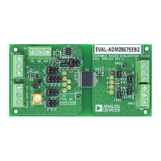
Page 3: Evaluation Board Photograph
EVAL-ADM2867EEBZ User Guide UG-1677 EVALUATION BOARD PHOTOGRAPH Figure 1. Rev. 0 | Page 3 of 12... -
Page 4: Evaluation Board Hardware
To power the V supply pin of the ADM2867E from the VCC P8 screw terminal block of the EVAL-ADM2867EEBZ. Test points terminal block and operate the V and V supply pins at the same are available on the EVAL-ADM2867EEBZ and are appropriately voltage, insert Jumper LK9. -
Page 5: En 55032 Radiated Emissions Test Results
ADM2867E ISOOUT ISOIN The EVAL-ADM2867EEBZ meets the EN 55032 and CISPR32 through the E2 ferrite bead. Class B requirements for radiated emissions with margin. The Place a 10 μF capacitor (C12) and a 0.1 μF capacitor (C8) -
Page 6: Other Board Components
LK3 jumper into Position BC. This setting connects the clock oscillator output The EVAL-ADM2867EEBZ has footprints for the RT1 and RT2 to the TxD input pin of the ADM2867E. termination resistors. Two 120 Ω termination resistors are fitted to... -
Page 7: Full Duplex Rs-485 Transceivers Loopback Test
Contact discharge implies direct contact between the discharge gun and the equipment under test (EUT). To set up a loopback test with the EVAL-ADM2867EEBZ, close the LK6 and LK7 jumpers. The test details are shown in Table 3 During air discharge testing, the charged electrode of the discharge and in Figure 5. - Page 8 UG-1677 EVAL-ADM2867EEBZ User Guide Table 3. Input Supply Configurations Jumper LK8 VREG_IN Input Voltage Range Supply Supply Not used Power V directly on connector P1 with a 3.3 V isolated output supply voltage between 3 V and 5.5 V High...
-
Page 9: Evaluation Board Schematic And Artwork
EVAL-ADM2867EEBZ User Guide UG-1677 EVALUATION BOARD SCHEMATIC AND ARTWORK Figure 6. EVAL-ADM2867EEBZ Schematic Rev. 0 | Page 9 of 12... - Page 10 UG-1677 EVAL-ADM2867EEBZ User Guide Figure 7. EVAL-ADM2867EEBZ Component Side, Layer 1 Figure 8. EVAL-ADM2867EEBZ, Layer 2 Figure 9. EVAL-ADM2867EEBZ, Silkscreen Rev. 0 | Page 10 of 12...
-
Page 11: Ordering Information
EVAL-ADM2867EEBZ User Guide UG-1677 ORDERING INFORMATION BILL OF MATERIALS Table 4. EVAL-ADM2867EEBZ Bill of Materials Reference Designator Description Manufacturer Part Number A, B, DE, INVD, INVR, RE, Test points, yellow Keystone Electronics 36-5004-ND RxD, TxD, Y, Z C1, C5, C7 to C9 Capacitors, 0.1 µF, 0402... - Page 12 (“Agreement”) unless you have purchased the Evaluation Board, in which case the Analog Devices Standard Terms and Conditions of Sale shall govern. Do not use the Evaluation Board until you have read and agreed to the Agreement. Your use of the Evaluation Board shall signify your acceptance of the Agreement. This Agreement is made by and between you (“Customer”) and Analog Devices, Inc.
Need help?
Do you have a question about the EVAL-ADM2867EEBZ and is the answer not in the manual?
Questions and answers