Table of Contents
Advertisement
Available languages
Available languages
Quick Links
Advertisement
Chapters
Table of Contents

Subscribe to Our Youtube Channel
Related Manuals for urmet domus 2 voice 1083


Summary of Contents for urmet domus 2 voice 1083
- Page 1 Mod. 1083 DS 1083-065 LBT 20103 SWITCHBOARD WITH 6 DIGIT ADDRESSING CENTRALE DE CONCIERGERIE AVEC ADDRESSAGE 6 DIGIT Ref. 1083/40C PQRS WXYZ SHIFT...
-
Page 2: Table Of Contents
ENGLISH INDEX GENERAL INFORMATION ..........................3 LIST OF DETAILS ............................3 Keypad ............................... 4 Ringer ................................. 4 Display ................................ 4 Usage types ..............................4 Switchboard off ............................ 4 Switchboard on ............................ 4 Night service ............................4 Day service ............................4 INSTALLATION ............................... -
Page 3: General Information
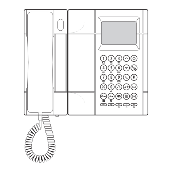
GENERAL INFORMATION The switchboard Ref. 1083/40C is only used in 2VOICE system to perform: — communication function to/from apartment stations, with capability to store not answered calls (up to 50); — concierge service (with or without local answer of calls coming from main call stations and addressed to apartment stations). -
Page 4: Keypad
KEYPAD The keypad includes dual function buttons used to enter call codes used to call apartment stations, special codes, call station codes used to open the door and search/enter user names. The functions of all the buttons are described in detail in next paragraphs. RINGER The ringer is electronically modulated and the volume can be adjusted on 5 levels, as described in the paragraph “Ringer Volume”. -
Page 5: Installation
INSTALLATION TABLE TOP INSTALLATION By default, the switchboard is confi gured for table top installation, with the specifi c support which ensures the best inclination. The wiring junction box must be wall mounted with the provided double-sided adhesive tape or with screws and screws anchors. - Page 6 Disconnect the fl at cable, noting the connector direction. DS1083-065...
-
Page 7: Video Module Installation
Connect the fl at cable, observing the connector insertion direction. The wiring junction box must be wall mounted with the provided double-sided adhesive tape or with screws and screws anchors. VIDEO MODULE INSTALLATION The video module, provided with the bracket Ref. 1732/91, can be installed on the right of the switchboard. - Page 8 Disconnect the fl at cable, noting the connector direction. Connect the fl at cable, observing the connector insertion direction. If the video module must be placed near a table top mounted switchboard, before starting operations described above, install the suitable support and the 2 feet provided with the video module bracket.
-
Page 9: Operating Instructions
OPERATING INSTRUCTIONS TURNING ON AND OFF THE SWITCHBOARD Case 1: switchboard without access password. To turn the switchboard on, press the button . The display shows: 1083/40C VER. X.X In this screen the software version number is indicated below. After 2 seconds, the switchboard starts operating in the mode active before it was turned off. If the switchboard is in working mode DAY, the led (2) is on;... -
Page 10: Standby
STANDBY 13/03/2010 15:30:30 During standby, the display only shows date and time. DISPLAYING NAME DIRECTORY AND CALLING A USER When pressing the buttons (18), the display shows the following screen NAME LIST: xxxx/nnnn yyyyyyyyyyyyyyyyyyyy yyyyyyyyyyyyyyyyyyyy 13/03/2010 15:30:30 where: xxxx progressive index of selected name nnnn total number of names in the directory yyyyyy... -
Page 11: Stored Calls Coming From Apartment Stations
STORED CALLS COMING FROM APARTMENT STATIONS If there is at least one stored call, the led of call memory (5) is on. When pressing the button (5), the following screen is displayed: MEM. CALL.: nn iiiii yyyyyyyyyyyyyyyyyyyy yyyyyyyyyyyyyyyyyyyy 13/03/2010 15:30:30 where: call progressive number in memory iiiii:... -
Page 12: Call From Main Station
where: iiiii: physical code of the called user (Liiii – in case of logical code) yyyyyy: name of the called user When the switchboard establishes a communication with the called user, the display shows the following screen: iiiii USER IN COMM.: iiiii yyyyyyyyyyyyyyyyyy yyyyyyyyyyyyyyyyyy... -
Page 13: Door Lock Release Function
the apartment station iiiii; if the attendant presses the button (7), the user iiiii is directly called and this symbol disappears. After receiving a call, the switchboard can call users by entering the code iiiii followed by the button (7). When in this condition, the switchboard attendant will be able to: –... -
Page 14: Management Of Codes For Special Services
In this example, the attendant has opened the door connected to the secondary call station with ID = 15 and secondary address 0. • When the switchboard is not in conversation, to open the driveway gate of a secondary call station press the button SHIFT (16) + (14) followed by the button (7), enter the ID code of the secondary call... -
Page 15: Keypad Lock Activation/Deactivation
required) with a main call station even if no one has called him from that station. To perform the auto-on function, press the button (10); the additional video module of the switchboard shows the image coming from the main call station with ID=0; to display images coming from the other additional cameras of the main station 0 and then images coming from other main call stations, press again the button (10). -
Page 16: Ringer Volume
RINGER VOLUME When the device is in standby mode, the ringer volume can be adjusted; for adjustment, keep the button SHIFT (16) pressed and select the desired volume (1÷5) with the buttons (18). During volume adjustment, the display shows the following screen: RING VOLUME: PRESS ↓↑... -
Page 17: Configuration
01 - L1000 CALL FOR: L1000 ROSSI 13/03/2010 15:30:30 — if the received physical code 14123 in the switchboard directory is NOT associated to any user, the display shows: 01 - 14123 CALL FOR: 14123 13/03/2010 15:30:30 CONFIGURATION To access the confi guration menu, keep the button SHIFT (16) pressed and press repeatedly and quickly the button (4). -
Page 18: Monitor Presence
To change the busy time, use the buttons (18). 8 different timings can be set: 1s, 10s, 20s, 30s, 40s, 50s, 60s, 70s. This value must be the same as that confi gured in system call stations. When the busy time has been selected, press the button (7) to confi... - Page 19 System configuration in column = YES System configuration in column = YES switchboard switchboard power supply power supply column interface power supply power supply call station call stations System configuration in column = YES door units switchboard power supply interface power supply power supply main call stations...
- Page 20 System configuration in column = NO column column secondary secondary interface interface call stations call stations power supply power supply switchboard power supply power supply main call station System configuration in column = NO secondary column column call interface interface stations secondary call stations...
-
Page 21: Call Repeat (S+, S-)
CALL REPEAT (S+, S-) In this screen the user can defi ne if the ringer repeat must be activated or not and if this must be activated only for special call types; the following screen appears: S+ S- (0=NO,1=EX,2=IN,3=A) The values selectable with the buttons (18) are: call repeat on S+ and S- disabled call repeat on S+ and S- enabled only for calls coming from main call stations... -
Page 22: User Codes Type
USER CODES TYPE In this screen it is possible to confi gure the user code type, physical or logical. — Physical code: users are called with a 5-digit code as follows: ccnnn, where cc indicates the riser column (from 00 a 31) and nnn indicates the number of the apartment (from 000 a 127) —... -
Page 23: Function Buttons
is displayed every time you change the N. DIGIT (N. DIGIT LOGICAL CODE) parameter value. Select 1 on the numeric keypad (12) to confi rm the parameter change. The screen with the new value will be displayed. N.DIGIT (0=4, 1=6) If the name database already contains some logical codes, these codes must be programmed again. -
Page 24: Name Management
F1 BUTTON TYPE SPECIAL CODE (0=NO,1=SPEC) Enter the special code to be associated to the button (1÷255) and press the button (7) to confi gure the next function button; • For buttons F4, F5, F6 only, select 2 to associate the divert call function to the button. The following screen will appear: F4 BUTTON TYPE DIVERTING CODE... - Page 25 Button 1 touch 2 touches 3 touches 4 touches 5 touches Blank Symbols can be selected with the buttons (18). When all data have been entered, press the button (7) to confi rm. When names are being entered, the following confi gurations are not accepted by the system: —...
-
Page 26: Diagnostic Services (Polling)
LIST DEL. DELETE ALL NAMES? (0=NO , 1=YES) Press 1 on the numeric keypad (12) to delete all the names or 0 to cancel the operation and return to the initial screen. The confi guration is kept even if the list is deleted. DIAGNOSTIC SERVICES (POLLING) This screen allows to poll apartment stations (AS), main call stations (MCM) and secondary call stations (SCM) present in the system:... - Page 27 AS POLL. PHYSICAL CODE: 21000 INTERNAL CODE.: ABSENT !! • By selecting with the buttons (18) the value 2, the display shows the following screen: MCM POLL. ID CODE: Enter the ID code of the secondary call station, press the button (7) to poll the device;...
-
Page 28: Default Values And Restore
Enter the ID code of the secondary call station, press the button (7), enter the address and press the button (7) to poll the device; after few seconds, the display will show the device status and FW version: SCM POLL. ID CODE: ADDRESS: PRESENT FW: 3.0... -
Page 29: Programming Via Pc
PROGRAMMING VIA PC The switchboard is provided with a USB port for easy programming of confi guration data and name directory. Access the confi guration menu by keeping the button SHIFT (16) pressed and pressing repeatedly and quickly the button (4). - Page 30 FRANÇAIS INDEX INFORMATIONS GÉNÉRALES ........................31 LISTE DES DÉTAILS ............................. 31 Clavier ............................... 32 Sonnerie ..............................32 Écran ................................ 32 Types d’utilisation ............................. 32 Centrale éteinte ..........................32 Centrale allumée ..........................32 Service nuit ............................32 Service jour ............................32 INSTALLATION .............................
-
Page 31: Informations Générales
INFORMATIONS GÉNÉRALES La centrale d’interphone Réf. 1083/40C est utilisée exclusivement dans le système 2VOICE pour réaliser: — le service de communication depuis/vers les postes internes, avec la capacité de mémorisation des appels non servis (jusqu’à 50); — le service de conciergerie (avec ou sans interception des appels provenant des postes d’appel principaux et adressés aux postes internes). -
Page 32: Clavier
CLAVIER Le clavier comprend des touches à double fonction pour la saisie des codes d’appel aux postes internes, des codes spéciaux, des codes des postes d’appel pour l’ouverture de la porte et pour la recherche/ saisie des noms des utilisateurs. Les fonctions des différentes touches sont décrites en détail dans les paragraphes suivants. -
Page 33: Installation
INSTALLATION INSTALLATION SUR TABLE La centrale sort de l’usine prête pour l’installation sur table, avec le support approprié qui en garantit une inclinaison idéale. La boîte de connexion doit être fi xée à la paroi avec le ruban adhésif double-face livré ou avec des vis et des chevilles. - Page 34 Débrancher le câble plat et prendre note de la direction du connecteur. DS1083-065...
-
Page 35: Installation Du Module Vidéo
Brancher le câble plat, respectant le sens d’introduction du connecteur. La boîte de connexion doit être fi xée à la paroi avec le ruban adhésif double-face livré ou avec des vis et des chevilles. INSTALLATION DU MODULE VIDÉO Le module vidéo, équipé d’un étrier Réf. 1732/955, peut être placé à la droite de la centrale. 1 –... - Page 36 Débrancher le câble plat et prendre note de la direction du connecteur. Brancher le câble plat, respectant le sens d’introduction du connecteur Si on désire placer le module vidéo à côté d’une centrale installée sur table, avant de commencer les opérations décrites ci-dessus, appliquer le support approprié et les 2 pieds livrés avec l’étrier du module vidéo.
-
Page 37: Instructions De Fonctionnement
INSTRUCTIONS DE FONCTIONNEMENT ALLUMAGE ET EXTINCTION Cas 1: centrale sans mot de passe d’accès. Pour mettre en service la centrale, appuyer sur la touche . L’écran affi che: 1083/40C VER. X.X En bas apparaît le numéro de version du logiciel. Après 2 secondes, la centrale entre en service dans le mode précédent à... -
Page 38: État De Repos
ÉTAT DE REPOS 13/03/2010 15:30:30 Pendant l’état de repos, l’écran affi che seulement la date et l’heure. AFFICHAGE DU RÉPERTOIRE DES NOMS ET APPEL D’UN UTILISATEUR En appuyant sur les touches (18), l’écran affi che: RÉPERTO.: xxxx/nnnn yyyyyyyyyyyyyyyyyyyy yyyyyyyyyyyyyyyyyyyy 13/03/2010 15:30:30 où: xxxx... -
Page 39: Appels Mémorosés Provenant Des Postes Internes
APPELS MÉMORISÉS PROVENANT DES POSTE INTERNES S’il y a au moins un appel mémorisé, la led de la mémoire des appels (5) est allumée. En appuyant sur la touche (5), l’écran affi che: MÉM. APPEL: nn iiiii yyyyyyyyyyyyyyyyyyyy yyyyyyyyyyyyyyyyyyyy 13/03/2010 15:30:30 où: numéro progressif de l’appel dans la mémoire... -
Page 40: Appel Provenant D'un Poste Principal
où: iiiii: code physique de l’utilisateur appelé (Liiii – en cas de code logique) yyyyyy: nom de l’utilisateur appelé Quand la centrale est en communication avec l’utilisateur appelé, l’écran affi che: iiiii UT. EN COMMUNIC: iiiii yyyyyyyyyyyyyyyyyy yyyyyyyyyyyyyyyyyy 13/03/2010 15:30:30 où: iiiii: code physique de l’utilisateur appelé... -
Page 41: Fonctions D'ouvre-Porte
Après avoir reçu un appel, la centrale peut appeler les utilisateurs en saisissant le code iiiii suivi de la touche (7). Depuis cette condition, le standardiste pourra: — rétablir une communication avec le poste d’appel — appeler de nouveau l’utilisateur —... -
Page 42: Gestion Des Codes Pour Services Spéciaux
Dans cet exemple, la porte qui s’est ouverte est celle associée au poste d’appel secondaire avec ID = 15 et adresse de secondaire 0. • quand la centrale N’est PAS en conversation, pour ouvrir le portail pour le passage des voitures d’un poste d’appel secondaire il faut appuyer sur la touche SHIFT (16) + (14), suivie de la touche (7),... -
Page 43: Fonction D'auto-Insertion
FONCTION D’AUTO-INSERTION La centrale équipée d’un module vidéo optionnel peut effectuer l’auto-insertion sur des postes d’appel principaux. Cela signifi e que le standardiste peut établir une connexion vidéo (et audio, si nécessaire) avec un poste d’appel principal même si personne ne l’a appelé depuis ce poste. Pour effectuer l’auto-insertion, appuyer sur la touche (10);... -
Page 44: Volume De La Sonnerie
Après avoir entré la dernière chiffre des secondes, confi rmer avec la touche (7). Si on ne veut pas changer les confi gurations de date/heure, appuyer sur la touche X (13) pendant 3 secondes. VOLUME DE LA SONNERIE Quand le dispositif est au repos, il est possible de régler le volume de la sonnerie; pour le réglage, rester appuyé... -
Page 45: Configuration
— si le code physique reçu 14123 correspond dans le répertoire de la centrale à l’utilisateur ROSSI avec code logique 1000, l’écran affi che: 01 - L1000 APPEL POUR: L1000 ROSSI 13/03/2010 15:30:30 — si le code physique reçu 14123 NE correspond dans le répertoire de la centrale à aucun utilisateur, l’écran affi... -
Page 46: Presénce Du Moniteur
TEMPS OCC. (1,10,20,30,...,70S) Pour changer le temps d’occupation, utiliser les touches (18). 8 temps différents peuvent être confi gurés: 1s, 10s, 20s, 30s, 40s, 50s, 60s, 70s. Ce temps doit être le même que celui confi guré dans les postes d’appel du système. Une fois sélectionné... - Page 47 Configuration système en colonne = OUI Configuration système en colonne = OUI centrale centrale alimentation alimentation interface de colonne alimentation alimentation poste d’appel poste d’appel Configuration système en colonne = OUI interface centrale postes alimentation externes alimentation alimentation postes d’appel principaux DS1083-065...
- Page 48 Configuration système en colonne = NON postes interface interface d’appel de colonne de colonne secondaires postes d’appel secondaires alimentation alimentation centrale alimentation alimentation postes d’appel principaux Configuration système en colonne = NON postes d’appel interface interface postes d’appel secondaires de colonne de colonne principaux alimentation...
-
Page 49: Répétition D'appel (S+, S-)
RÉPÉTITION D’APPEL (S+, S-) Dans cette page-écran il est possible de défi nir si la répétition de la sonnerie doit être activée ou non et si elle doit être activée seulement pour certains types d’appel; l’écran affi che: S+ S- (0=NO,1=EX,2=IN,3=T) Les valeurs qui peuvent être sélectionnées avec les touches (18) sont:... -
Page 50: Types De Codes Utilisateur
Le mot de passe peut être composé de 6 caractères numériques au maximum. Si on ne désire pas protéger l’allumage de la centrale avec un mot de passe, il faut le confi gurer à 000000. Une fois le paramètre confi guré, appuyer sur la touche (7) pour confi... -
Page 51: Touches Fonction
La demande de confi rmation N. CHIFFRES CONF? 0=N0N, 1=OUI s’affi che à chaque fois que le paramètre N. CHIFFRES (N. CHIFFRES CODE LOGIQUE) est modifi é. Pour confi rmer la modifi cation du paramètre, sélectionner 1 sur le clavier numérique (12). Ensuite, la page s’affi... -
Page 52: Gestion Des Noms
F1 FONCT. (0=NO,1=SPÉC) Pour confi gurer ce paramètre, utiliser les touches (18): • en sélectionnant la valeur 0, aucune fonction spéciale ne sera associée à la touche, • en sélectionnant la valeur 1 la fonction d’envoi de code spécial sera associée à la touche et l’écran affi... - Page 53 INTR. NOM PHYS:00012 LOG:1000 ROSSI PAOLO En utilisant le clavier alphanumérique, saisir le code physique suivi de la touche (7), le code logique (qui n’est pas demandé si le dispositif est programmé pour utiliser des codes physiques) suivi de la touche (7) et enfi...
-
Page 54: Services De Diagnostic (Polling)
Pour effacer un nom, sélectionner 3 dans le clavier numérique (12): • EFF. NOM 0001/0083 PHYS:00012 LOG:1000 ROSSI PAOLO En utilisant les touches (18), faire défi ler la liste, sélectionner le nom qui doit être effacé et appuyer sur la touche (7). - Page 55 Saisir le code physique du poste interne, appuyer sur la touche (7), saisir le code interne et appuyer sur la touche (7) pour interroger le dispositif; dans quelques secondes, l’écran affi chera l’état du dispositif avec sa version FW: PI POLLING CODE PHYSIQUE: 21000 CODE INT.: ABSENT FW: 3.0...
-
Page 56: Valeurs Implicites Et Leur Restauration
• En sélectionnant la valeur 3 avec les touches (18), l’écran affi che: MAS POLLING CODE ID: ADRESSE: Saisir le code ID du poste d’appel secondaire et appuyer sur la touche (7), entrer l’adresse et appuyer sur la touche (7) pour interroger le dispositif; dans quelques secondes, l’écran affi chera l’état du dispositif avec sa version FW: MAS POLLING CODE ID:... -
Page 57: Programmation Par Pc
PROGRAMMATION PAR PC La centrale est équipée d’un port USB pour la programmation facilitée de la confi guration et du répertoire des noms. Entrer dans le menu de confi guration en restant appuyé sur la touche SHIFT (16) et appuyer plusieurs fois et rapidement sur la touche (4). -
Page 58: System Diagrams
DIAGRAMS NOTES V5.020 - Cut the wires (projecting VD.007 - Floor call button. from the adapter) to use the connector again. VV.004 - Note: on the last column Then insert the connected in the interface do not remove the adapter socket. jumper between terminal Follow the tables below for pins Z. - Page 59 NOTES DES SCHÉMAS V5.020 - Il est nécessaire de couper VD.007 - Touche dʼappel à lʼétage. les conducteurs (qui sortent de lʼadaptateur) de façon à pouvoir VV.004 - Remarque: sur la dernière réutiliser le connecteur. Ensuite, interface de colonne, il ne brancher le connecteur à...
- Page 60 Connection of N columns, each one with 4 risers of several video door phones or door phones to 4 main electric video door entrance panels (VPE) and to 1 concierge switchboard with video module. Each column is also connected to 1 or 2 secondary VPE. Connexion de N colonnes, chacune avec 4 dorsales au max., de plusieurs vidéophones et interphones, à...
- Page 61 "5" "6" "7" "8" DS1083-065...
- Page 62 Connection of N columns, each one with 4 risers of N video door phones and door phones to 1 main electric video door entrance panel (VPE) and to 1 concierge switchboard with video module. Each group is also connected to 1 or 2 secondary VPE. Connexion de N colonnes, chacune avec 4 dorsales au max., de N vidéophones et interphones, à...
- Page 63 "5" "6" "7" "8" DS1083-065...
- Page 64 Connection of 1 riser of video door phones and door phones to 1 video entrance panel (VEP) and to 1 concierge switchboard with video module. Connexion d’1 dorsale de vidéophones et d’interphones à 1 portier électrique vidéo (PEV) et à 1 centrale de conciergerie avec module vidéo.
- Page 65 Connecting the video module Ref. 1732/41 and the bracket Ref. 1732/955 with a video adapter Ref. 1742/13A to the 2Voice switchboard. Branchement du module vidéo Réf. 1732/41 et étrier Réf. 1732/955 avec adaptateur Réf. 1742/13A à la centrale de conciergerie 2Voice. SV 124-1260A LINE OUT LINE...
- Page 66 LEGENDA A - Column A - Colonne B - Riser B - Montant C - To the next distributors C - Vers les autres distibuteurs D - Ref. 1083/55 D - Réf. 1083/55 4-user distributor Distributeur á 4 utilisateurs E - Ref. 1072/59 E - Réf.
- Page 67 DS1083-065...
- Page 68 DS 1083-065 LBT 20103 URMET S.p.A. Area tecnica 10154 TORINO (ITALY) servizio clienti +39 011.23.39.810 VIA BOLOGNA 188/C http://www.urmet.com Telef. +39 011.24.00.000 (RIC. AUT.) e-mail: info@urmet.com +39 011.24.00.300 - 323...
Need help?
Do you have a question about the 2 voice 1083 and is the answer not in the manual?
Questions and answers