urmet domus IPerCom VOG 7 Installation Handbook
Video door phone 7 ip
Hide thumbs
Also See for IPerCom VOG 7:
- Booklet (36 pages) ,
- Quick user manual (20 pages) ,
- System technical manual for the installer (712 pages)
Table of Contents
Advertisement
Available languages
Available languages
Quick Links
DS 1761-004B
(bianco / white / blanc / blanco / weiß / wit)
(nero / black / noire / negro / schwarz / zwart)
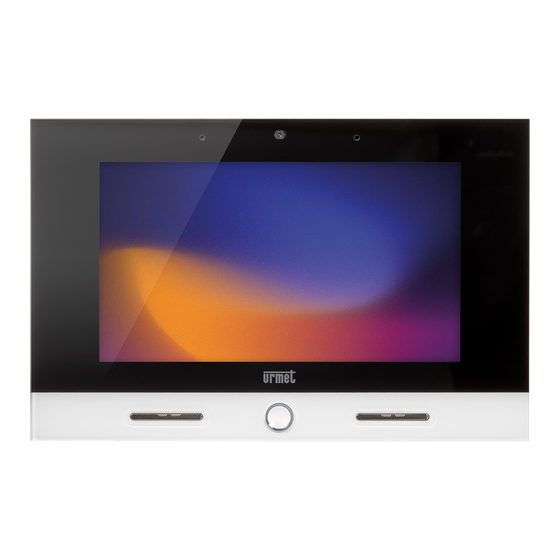
VIDEOCITOFONO 7" IP
VIDEO DOOR PHONE 7" IP
MONITEUR 7" IP
VIDEOINTERFONO 7" IP
7" IP-VIDEOSPRECHANLAGE
7" IP-BEELDINTERCOM
Sch./Ref. 1761/31
Sch./Ref. 1761/33
LIBRETTO INSTALLAZIONE
INSTALLATION HANDBOOK
NOTICE D'INSTALLATION
MANUAL DE INSTALACIÓN
INSTALLATIONSANLEITUNG
INSTALLATIEHANDLEIDING
Mod.
1761
LBT 20890
Advertisement
Table of Contents

Subscribe to Our Youtube Channel
Related Manuals for urmet domus IPerCom VOG 7


Summary of Contents for urmet domus IPerCom VOG 7
- Page 1 Mod. 1761 DS 1761-004B LBT 20890 VIDEOCITOFONO 7” IP VIDEO DOOR PHONE 7” IP MONITEUR 7” IP VIDEOINTERFONO 7” IP 7” IP-VIDEOSPRECHANLAGE 7” IP-BEELDINTERCOM Sch./Ref. 1761/31 (bianco / white / blanc / blanco / weiß / wit) Sch./Ref. 1761/33 (nero / black / noire / negro / schwarz / zwart) LIBRETTO INSTALLAZIONE INSTALLATION HANDBOOK NOTICE D’INSTALLATION...
- Page 2 ITALIANO ATTENZIONE! Per il funzionamento del dispositivo è necessario che la versione del firmware del sistema Ipercom sia la 2.1.0 o superiore. L’aggiornamento della versione del firmware del sistema Ipercom è disponibile sul sito Urmet alla sezione Download/Software (previa registrazione). Il videocitofono IP Sch.1761/31 o /33, è...
-
Page 3: Installazione
3. INSTALLAZIONE • Murare la scatola incasso Mod. 503 o la scatola a incasso Ø 60 all’altezza indicata nel disegno seguente. La scatola a incasso Mod. 503 può essere installata sia in orizzontale che in verticale. Scatola Scatola Ø 60 mm (*) Nel caso di persone con disabilità... - Page 4 4. ISTRUZIONI DI CABLAGGIO Cavo Ethernet con connettore RJ45 Il sistema IperCom è sviluppato per il funzionamento con lo standard EIA/TIA 568B. • Inserire il cavo su uno dei connettori RJ45 con logo Urmet. • Inserire il conduttore nella guida, rispettando le colorazioni indicate (Standard T568B). Guaina nera Conduttore Colore cavo...
-
Page 5: Caratteristiche Tecniche
5. CONFIGURAZIONE DISPOSITIVO Per la configurazione del dispositivo consultare il manuale tecnico di sistema scansionando il seguente QR Code con la fotocamera del proprio smartphone o tablet. 6. CARATTERISTICHE TECNICHE Tensione di alimentazione POE: ..................... 48-54 V : ................48 V - min. - Page 6 ENGLISH IMPORTANT The firmware version of the Ipercom system must be 2.1.0 or higher for the operation of the device. The firmware version update of the Ipercom system is available on the Urmet website in the Download/Software section (registration required). The IP video door phone Ref.1761 /31 or /33 is a device dedicated to Ipercom system.
-
Page 7: Installation
3. INSTALLATION • Embed the flush-mounting box Mod. 503 in the wall or the flush-mounting box Ø 60 at the height shown in the following drawing. The flush-mounting box Mod. 503 can be installed either horizontally or vertically. Box 503 Box Ø... -
Page 8: Wiring Instructions
4. WIRING INSTRUCTIONS Ethernet RJ45 wire Ipercom system is developed for to work with the EIA/TIA 568B standard. • Plug the cable into one of the RJ45 connectors with the Urmet logo. • Insert the wire in its guide, according to the provided colour code (Standard T568B). Black sheath Wire Cable colour... -
Page 9: Device Configuration
5. DEVICE CONFIGURATION Refer to the technical system manual by scanning the following QR Code with the camera of your smartphone or tablet to configure the device. 6. TECHNICAL SPECIFICATIONS POE input voltage: ......................... 48-54 V :..................48 V - min. 15 W External power supply voltage Max consumption: ............................ - Page 10 FRANÇAIS ATTENTION ! Pour le fonctionnement du dispositif, il est nécessaire que la version du micrologiciel du système IperCom soit la version 2.1.0 ou supérieure. La mise à jour de la version du micrologiciel du système Ipercom est disponible sur le site Urmet, dans la section Téléchargement/Logiciels (après enregistrement).
- Page 11 3. INSTALLATION • Emmurer le boîtier à encastrer Mod. 503 ou le boîtier à encastrer Ø 60 à la hauteur indiquée dans la figure suivante. Le boîtier à encastrer Mod. 503 peut être installé en position horizontale ou verticale. Boîtier Boîtier Ø...
-
Page 12: Instructions De Câblage
4. INSTRUCTIONS DE CÂBLAGE Câble Ethernet RJ45 Le système Ipercom est dèveloppé pour fonctionner sous le standard EIA/TIA 568B. • Brancher le câble à un des connecteurs RJ45 marqué du logo Urmet. • Introduire le conducteur dans le guide en veillant à respecter les couleurs indiquées (Standard T568B). Gaine noire Conducteur Couleur câble... -
Page 13: Configuration Du Dispositif
5. CONFIGURATION DU DISPOSITIF Pour la configuration du dispositif, se reporter au manuel technique du système, après lecture du QR Code suivant à l’aide de la caméra d’un smartphone ou d’une tablette. 6. CARACTERISTIQUES TECHNIQUES Tension d’alimentation POE: ......................48-54 V : .................. - Page 14 ESPAÑOL ¡ATENCIÓN! Para el funcionamiento del dispositivo es necesario que la versión del firmware del sistema Ipercom sea la 2.1.0 o superior. La actualización de la versión del firmware del sistema Ipercom se encuentra en el sitio Urmet, en la sección Descargar/Software (después de registrarse). El videocitòfono IP Ref.
-
Page 15: Instalación
3. INSTALACIÓN • Empotrar la caja Mod. 503 o la caja Ø 60 a la altura indicada en la figura siguiente. La caja para empotrar Mod. 503 se puede instalar en horizontal o en vertical. Caja Caja Ø 60 mm •... -
Page 16: Instrucciones De Cableado
4. INSTRUCCIONES DE CABLEADO Cable Ethernet RJ45 El sistema Ipercom se desarrolló para trabajar con el estándar EIA/TIA 568B. • Introduzca el cable en uno de los conectores RJ45 con el logo de Urmet. • Introduzca el conductor en la guía, respetando los colores indicados (estándar T568B) Vaina negra Conductor Color del cable... -
Page 17: Configuración Del Dispositivo
5. CONFIGURACIÓN DEL DISPOSITIVO Para la configuración del dispositivo, consultar el manual técnico del sistema escaneando el siguiente Código QR con la cámara del smartphone o de la tableta. 6. CARACTERÍSTICAS TÉCNICAS Tensión de alimentación POE: ....................... 48-54 V : ................. 48 V - min. - Page 18 DEUTSCH ACHTUNG! Für die korrekte Funktionsweise des Geräts ist es erforderlich, dass die Firmware-Version des Ipercom-Systems 2.1.0 oder höher vorliegt. Die Aktualisierung der Firmware-Version des Ipercom-Systems steht auf der Website von Urmet im Bereich Download/Software zur Verfügung (nach Anmeldung). Die IP-Videosprechanlage BN 1761/31 oder /33 ist ein für das Ipercom-System bestimmtes Gerät. Für einen einwandfreien Betrieb des Geräts ist eine LAN/POE-Verbindung erforderlich.
- Page 19 3. INSTALLATION • Das Einbaugehäuse Mod. 503 oder die Unterputzdose Ø 60 auf der in der nachstehenden Zeichnung angegebenen Höhe vermauern. Die Unterputzdose Mod. 503 kann sowohl horizontal als auch vertikal installiert werden. Gehäuse Gehäuse Ø 60 mm • An den auf der externen Leiterplatte vorhandenen Klemmen die eventuellen Leiter der Panikfunktion, des zusätzlichen Läutwerks, des Etagenrufs, der Hilfsversorgung, des Anschlusses am IPerHOME- System anschließen.
- Page 20 4. VERKABELUNGSANLEITUNG Ethernet-Kabel RJ45 Das Ipercom-System ist für einen Betrieb nach dem Standard EIA/TIA 568B konzipiert. • Das Kabel an einem der RJ45-Steckverbinder mit Urmet-Logo einstecken. • Den Leiter unter Berücksichtigung der genannten Farbgebungen (Standard T568B) in die Führung einführen. Schwarzer Mantel Leiter Nr.
-
Page 21: Technische Eigenschaften
5. GERÄTEKONFIGURATION Hinsichtlich der Gerätekonfiguration das technische Systemhandbuch konsultieren und dazu den folgenden QR-Code mit der Kamera Ihres Smartphones oder Tablets einscannen. 6. TECHNISCHE EIGENSCHAFTEN POE-Versorgungsspannung: ......................48-54 V : ................... 48 V - min. 15 W Externe Versorgungsspannung Max. Verbrauch: ............................12 W Ausgang Klemmen S+, S-: .................... - Page 22 NEDERLANDS OPGELET! Het toestel kan alleen werken als de firmwareversie van het Ipercom-systeem 2.1.0 of hoger is. U kunt de firmware-versie van het Ipercom-systeem bijwerken op de site van Urmet in het gedeelte Download/Software (mits u eerst registreert). De IP Beeldintercom Sch.1761/31 of /33 is voorbehouden voor het Ipercom-systeem. Om te zorgen dat het systeem correct werkt, is er een LAN/PoE-aansluiting nodig.
- Page 23 3. INSTALLATIE • Inbouwdoos Mod. 503 of de inbouwdoos Ø 60 inbouwen op de op de volgende tekening aangeduide hoogte. De inbouwdoos Mod. 503 kan zowel horizontaal als verticaal worden geïnstalleerd. Doos Doos Ø 60 mm • Sluit de eventuele stekkers van de paniekfunctie, de extra bel, de oproep naar etage, de extra voeding en de aansluiting op het IPerHOME-systeem aan op de klemmen die op de externe printplaat aanwezig zijn.
- Page 24 4. AANWIJZIGINGEN VOOR DE BEDRADING Ethernetkabel RJ45 Het Ipercom-systeem is ontwikkeld om te functioneren met de standaard EIA/TIA 568B. • Plaats de kabel op een van de RJ45 stekkers met het Urmet-logo. • Steek de stekker in de geleiding, met inachtneming van de kleurcode (Standaard T568B) Zwarte kabelmantel Stekker nr.
-
Page 25: Technische Kenmerken
5. CONFIGURATIE VAN HET TOESTEL Voor de configuratie van het toestel raadpleegt u de technische handleiding van het systeem die u downloadt met de QR-code met de camera van uw smartphone of tablet. 6. TECHNISCHE KENMERKEN PoE voedingsspanning: ........................48-54 V : .................. - Page 26 ITALIANO DIRETTIVA 2012/19/UE DEL PARLAMENTO EUROPEO E DEL CONSIGLIO del 4 luglio 2012 sui rifiuti di apparecchiature elettriche ed elettroniche (RAEE) Il simbolo del cassonetto barrato riportato sull’apparecchiatura o sulla sua confezione indica che il prodotto alla fine della propria vita utile deve essere raccolto separatamente dagli altri rifiuti. L’utente dovrà, pertanto, conferire l’apparecchiatura giunta a fine vita agli idonei centri comunali di raccolta differenziata dei rifiuti elettrotecnici ed elettronici.
- Page 27 ESPAÑOL DIRECTIVA 2012/19/UE DEL PARLAMENTO EUROPEO Y DEL CONSEJO del 4 de julio de 2012 sobre residuos de aparatos eléctricos y electrónicos (RAEE) El símbolo del contenedor de basura tachado con un aspa en el producto, o en su embalaje, indica que dicho producto no debe desecharse junto con los otros residuos domésticos.
- Page 28 DS 1761-004B LBT 20890 URMET S.p.A. Area tecnica 10154 TORINO (ITALY) servizio clienti +39 011.23.39.810 VIA BOLOGNA 188/C http://www.urmet.com Telef. +39 011.24.00.000 (RIC. AUT.) e-mail: info@urmet.com +39 011.24.00.300 - 323 MADE IN CHINA...
Need help?
Do you have a question about the IPerCom VOG 7 and is the answer not in the manual?
Questions and answers