urmet domus 1760 Installation Handbook
2voice hands-free wifi video door phone black/white works with alexa
Hide thumbs
Also See for 1760:
- User booklet (64 pages) ,
- Configuration booklet (44 pages) ,
- Quick manual (4 pages)
Table of Contents
Advertisement
Available languages
Available languages
Advertisement
Table of Contents

Related Manuals for urmet domus 1760


Summary of Contents for urmet domus 1760
- Page 1 Mod. 1760 DS1760-043 LBT21224 VIDEOCITOFONO 2VOICE VIVAVOCE WiFi 2VOICE HANDS-FREE WIFI VIDEO DOOR PHONE Sch./Ref. 1760/15 (nero / black) Sch./Ref. 1760/16 (bianco / white) LIBRETTO DI INSTALLAZIONE INSTALLATION HANDBOOK...
-
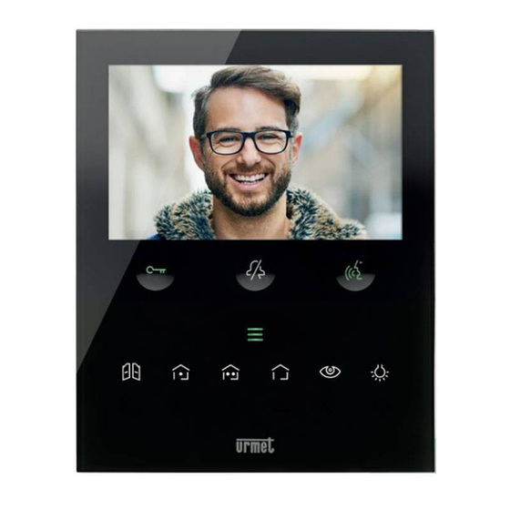
Page 2: Descrizione Generale
ITALIANO DESCRIZIONE GENERALE I videocitofoni Sch. 1760/15 e Sch. 1760/16 sono dedicati all’utilizzo in impianti videocitofonici del sistema 2Voice. Le caratteristiche principali sono: • schermo a colori TFT-LCD da 5’’ (Wide Angle); • pulsanti soft-touch retroilluminati (*); • possibilità di attivazioni delle funzioni del videocitofono tramite comandi gestuali sul sensore IR (di default disabilitate);... - Page 3 : tasto attivazione comando Yokis 2 e nello stesso tempo chiusura del contatto presente tra i morsetti Y1 e Y2 (max 50 mA @ 24 V ) : tasto menu pulsanti Yokis : tasto autoinserzione / palleggiamento video : tasto funzione speciale : tasto chiamata intercomunicante : tasto freccia scorrimento verso sinistra : tasto freccia scorrimento verso destra...
-
Page 4: Installazione
INSTALLAZIONE ATTENZIONE! Per un corretto funzionamento dei comandi gestuali (Gesture), non installare il dispositivo in luoghi in cui può essere esposto direttamente ai raggi solari, in quanto il sensore IR è sensibile alla luce. • Murare la scatola incasso Mod. 503 o la scatola a incasso Ø 60 all’altezza indicata nel disegno seguente. La scatola a incasso Mod. 503 può essere installata sia in orizzontale che in verticale. • Fissare la staffa alla scatola incasso o al muro come indicato. -
Page 5: Descrizione Dei Morsetti
3.1. DESCRIZIONE DEI MORSETTI Morsettiera sinistra Morsetti per alimentatore locale Sch. 1723/22 Negativo per suoneria supplementare Positivo per suoneria supplementare Pulsante Pulsante Morsettiera destra Chiamata al piano PANIC Allarme panico LINE OUT Uscita BUS alimentazione LINE IN Ingresso BUS alimentazione 3.2. JUMPER E DIP-SWITCH SW1 N.1 (DEFAULT) DS1760-043... - Page 6 JUMPER (JP3) Il seguente Jumper permette la regolazione della terminazione di linea (Z) nel caso di collegamento del videocitofono in entra-esci. La terminazione di linea deve essere inserita sull’ultimo videocitofono. Terminazione inserita (default) Terminazione non inserita Per la posizione dei jumper JP1 e JP2 e del dip-switch SW1 n.1 fare riferimento al capitolo successivo del seguente libretto.
- Page 7 DS1760-026” sul sito Urmet scansionando il seguente QR Code. Se il videocitofono Sch. 1760/15 o /16 viene installato come ricambio in sostituzione ad un altro videocitofono è necessario che venga alimentato tramite l’alimentatore locale e configurato con la modalità di utilizzo Alimentatore locale.
- Page 8 6. INSERIMENTO CONTATTI PER CHIAMATE INTERCOMUNICANTI Per poter effettuare delle chiamate intercomunicanti è necessario inserire dei contatti nella rubrica videocitofonica. È possibile inserire fino a 32 contatti. Per inserire un nuovo contatto seguire la seguente procedura: • Premere 2 volte il tasto quando il videocitofono è a riposo per accendere il display e visualizzare la Homepage.
- Page 9 • Premere il tasto per confermare la selezione. • Per inserire un nuovo contatto premere il tasto e selezionare l’icona di aggiunta nuovo contatto • Premere il tasto per confermare e visualizzare sul display la seguente schermata: • Per ogni nuovo contatto è necessario definire i seguenti parametri: Tipologia di contatto Premere il tasto per selezionare la seguente icona , successivamente premere il tasto...
- Page 10 Nel menu di configurazione alla voce “Informazioni di sistema” è possibile visualizzare il codice ID dei videocitofoni (per maggiori dettagli vedere il Libretto di configurazione parametri disponibile scansionando il QR-Code presente alla fine del libretto. Premere i tasti per selezionare sulla tastiera virtuale i numeri che compongono il codice ID del videocitofono che si desidera inserire nei contatti.
- Page 11 7. RIPRISTINO AI PARAMETRI DI FABBRICA Per ripristinare il dispositivo ai parametri di fabbrica seguire la seguente procedura: • Premere 2 volte il tasto quando il videocitofono è a riposo per accendere il display e visualizzare la Homepage. • Premere i tasti per selezionare la seguente icona •...
- Page 12 • Il display visualizza la seguente schermata: Premendo i tasti è possibile selezionare quali parametri del videocitofono si desidera riportare ai valori di fabbrica. Dopo aver effettuato la selezione premere il tasto per abilitare o disabilitare il parametro al ripristino ai dati di fabbrica. L’abilitazione è confermata dalla presenza dell’icona di fianco al nome del parametro.
-
Page 13: Caratteristiche Tecniche
10. DICHIARAZIONE DI CONFORMITÀ UE SEMPLIFICATA Il fabbricante, URMET S.p.A., dichiara che il tipo di apparecchiatura radio: VIDEOCITOFONO 2VOICE VIVAVOCE WiFi Sch. 1760/15 o 1760/16 è conforme alla direttiva 2014/53/UE. Il testo completo della dichiarazione di conformità UE è disponibile al seguente indirizzo Internet: www.urmet.com... -
Page 14: General Description
ENGLISH GENERAL DESCRIPTION The video door phones Ref. 1760/15 and Ref. 1760/16 are dedicated to use in 2Voice video door phone systems. The main features are: • colour 5’’ TFT-LCD screen (Wide Angle); • backlit soft-touch buttons (*); • possibility of activating video door phone functions via gesture commands on the IR detector (disabled by default);... - Page 15 Yokis 1 command setting key and closing, at the same time, of the contact between terminals Y1 and Y2 (max. 50 mA @ 24 V ) : Yokis key menu key : auto-on / video switching key : special function key : intercom call key : left scrolling arrow key : right scrolling arrow key...
-
Page 16: Installation
INSTALLATION ATTENTION! For proper operation of the Gesture commands, do not install the device in places where it may be exposed to direct sunlight, as the IR detector is sensitive to light. • Install the flush-mounting box Mod. 503 or the flush-mounting box Ø 60 at the height indicated in the following drawing. The flush-mounting box Mod. 503 can be horizontally or vertically installed. • Fix the bracket to the mounting box as indicated. -
Page 17: Terminal Description
3.1. TERMINAL DESCRIPTION Left terminal board Terminals for local power supply unit Ref. 1723/22 Negative for additional chime Positive for additional chime Button Button Right terminal board Floor call PANIC Panic alarm LINE OUT Power supply BUS output LINE IN Power supply BUS input 3.2. JUMPER AND DIP-SWITCH SW1 NO.1 (DEFAULT) DS1760-043... - Page 18 JUMPER (JP3) The following Jumper allows to adjust the line termination (Z) in case of in-out video door phone connection. The line termination must be inserted into the last video door phone. Termination inserted (default) Termination not inserted For position of jumpers JP1 and JP2 and dip-switch SW1 no.1 refer to the next chapter of the following handbook.
- Page 19 DS1760-026” on the Urmet website by scanning the following QR Code. If the video door phone Ref. 1760/15 or /16 is installed as a spare to replace a video door phone, it must be powered through the local power supply and configured with the local power mode of use.
- Page 20 6. CONTACT INSERTION FOR INTERCOM CALLS In order to make intercom calls, it is necessary to enter contacts in the video door phone book. Up to 32 contacts can be entered. To enter a new contact, proceed as follows: • Press the key twice when the video door phone is in stand-by mode to turn on the display and view the Homepage. For video door phones powered in High rise block and Low rise block, access to the Homepage is permitted to one device at a time, for a maximum of 5 minutes.
- Page 21 • To enter an new contact, press the key and select the icon to add a new contact • Press the key to confirm and display the following screen: • The following parameters must be defined for each new contact: Contact type Press the key to select the following icon , then press the key to change the contact type.
- Page 22 Press the keys to select on the virtual keypad the numbers that make up the video door phone ID code you want to add to the contacts. Press the key to confirm the selected number. Contact name Press the keys to select the following icon , then press the key to enter the contact name.
-
Page 23: Reset To Factory Settings
7. RESET TO FACTORY SETTINGS To reset the device to factory settings, proceed as follows: • Press the key twice when the video door phone is in stand-by mode to turn on the display and view the Homepage. • Press keys to select the following icon •... - Page 24 • The display shows the following screen: Press the keys to select which video door phone parameters you want to reset to factory values. When the selection has been made, press the key to enable or disable the parameter for reset to factory data. Enabling is confirmed by the presence of the icon next to the parameter name.
-
Page 25: Technical Specifications
10. SIMPLIFIED EU DECLARATION OF CONFORMITY Hereby, URMET S.p.A. declares that the radio equipment type: 2VOICE HANDS-FREE WiFi VIDEO DOOR PHONE Ref. 1760/15 or 1760/16 is in compliance with Directive 2014/53/EU. The full text of the EU declaration of conformity is available at the following internet address: www.urmet.com... - Page 26 ITALIANO DIRETTIVA 2012/19/UE DEL PARLAMENTO EUROPEO E DEL CONSIGLIO del 4 luglio 2012 sui rifiuti di apparecchiature elettriche ed elettroniche (RAEE) Il simbolo del cassonetto barrato riportato sull’apparecchiatura o sulla sua confezione indica che il prodotto alla fine della propria vita utile deve essere raccolto separatamente dagli altri rifiuti. L’utente dovrà, pertanto, conferire l’apparecchiatura giunta a fine vita agli idonei centri comunali di raccolta differenziata dei rifiuti elettrotecnici ed elettronici. In alternativa alla gestione autonoma è possibile consegnare l’apparecchiatura che si desidera smaltire al rivenditore, al momento dell’acquisto di una nuova apparecchiatura di tipo equivalente. Presso i rivenditori di prodotti elettronici con superficie di vendita di almeno 400 m...
- Page 27 DS1760-043...
- Page 28 FUNZIONE DI INOLTRO DI CHIAMATA Di seguito vengono elencate le varie azioni da eseguire per abilitare la funzione in modo facile e veloce: 1. INSTALLATORE — Configurazione e fase di test della funzione sul videocitofono per mezzo dell’App CallMe Set. — Abilitazione al funzionamento del videocitofono. 2. UTENTE — Creazione di un account per mezzo dell’App CallMe. —...
Need help?
Do you have a question about the 1760 and is the answer not in the manual?
Questions and answers