Table of Contents
Advertisement
Available languages
Available languages
Quick Links
DS 1083-067
CENTRALINO DI PORTINERIA CON INDIRIZZAMENTO 6 DIGIT
CONCIERGE SWITCHBOARD WITH 6 DIGIT ADDRESSING
PER LA CONFIGURAZIONE E IL FUNZIONAMENTO
DI DUE CENTRALINI 1083/40C IN MODALITÀ MUTUAMENTE ESCLUSIVA
FOR THE CONFIGURATION AND OPERATION OF TWO 1083/40C
SWITCHBOARDS IN MUTUALLY EXCLUSIVE MODE (X-OR) IN 2 VOICE SYSTEM
(La documentazione in lingua francese, spagnola e tedesca è scaricabile dal sito www.urmet.com)
(Manuals in French, Spanish and German can be downloaded from www.urmet.com)
Sch./Ref. 1083/40C
ADDENDUM
(X-OR) CON SISTEMA 2 VOICE
ADDENDUM
1
2
3
ABC
DEF
4
5
6
GHI
JKL
MNO
7
8
9
PQRS
TUV
WXYZ
0
SHIFT
F1
F2
F3
F4
F5
F6
Mod.
1083
LBT 20106
Advertisement
Chapters
Table of Contents

Related Manuals for urmet domus 1083/40C


Summary of Contents for urmet domus 1083/40C
- Page 1 WXYZ SHIFT ADDENDUM PER LA CONFIGURAZIONE E IL FUNZIONAMENTO DI DUE CENTRALINI 1083/40C IN MODALITÀ MUTUAMENTE ESCLUSIVA (X-OR) CON SISTEMA 2 VOICE ADDENDUM FOR THE CONFIGURATION AND OPERATION OF TWO 1083/40C SWITCHBOARDS IN MUTUALLY EXCLUSIVE MODE (X-OR) IN 2 VOICE SYSTEM (La documentazione in lingua francese, spagnola e tedesca è...
-
Page 2: Table Of Contents
ITALIANO INDICE INTRODUZIONE ............................. 2 RICHIAMI ISTRUZIONI OPERATIVE ....................... 2 2.1 Elenco dei particolari ........................3 2.2 Procedura per accedere al menu ....................3 2.3 Procedura per uscire dal menu ....................... 3 2.4 Struttura del menu .......................... 4 2.5 Procedura di ripristino ai valori di default ..................4 2.6 Procedura di disattivazione funzione deviazione di chiamata su cordless ........ -
Page 3: Elenco Dei Particolari
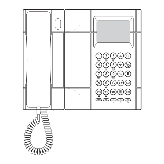
2.1 ELENCO DEI PARTICOLARI PQRS WXYZ SHIFT PQRS WXYZ SHIFT Tasto di accensione e spegnimento con led verde Tasto di commutazione servizio giorno/notte con led verde Tasto per visualizzare l’elenco delle porte rimaste aperte con led rosso Tasto attivazione fonia verso posto interno Tasto per visualizzare la memoria chiamate dai posti interni con led rosso Tasto attivazione comunicazione tra posto esterno e posto interno Tasto per chiamate/conferme... -
Page 4: Struttura Del Menu
2.4 STRUTTURA DEL MENU Di seguito si riporta, per comodità, la struttura del menù. LINGUA TEMPO OCC. MONITOR ITALIANO (1,10,20,30,...,70S) (0=NO , 1=SI) IN COLONNA S+ S- INTERROMP. (0=NO , 1=SI) (0=NO,1=ES,2=IN,3=T) (0=NO , 1=SI) PASSWORD TIPO COD. F1 FUNZ. 000000 (0=FISICO, 1=LOGICO) (0=NO,1=SPEC,2=TEL) -
Page 5: Configurazione Parametri Impianto
CONFIGURAZIONE PARAMETRI IMPIANTO Al fi ne di utilizzare due centralini nello stesso impianto è necessario assegnare a ciascuno di essi un identifi cativo univoco. Per il corretto funzionamento assicurarsi che entrambi i centralini abbiano il parametro IN COLONNA impostato a 0. In caso di errata impostazione su uno dei due centralini il trasferimento di competenza non sarà... -
Page 6: Installazione Dei Centralini
Il centralino non attivo ha una sola modalità di funzionamento in cui non fa nulla tranne che ricevere la competenza (se richiesto dal centralino attivo). Il centralino non attivo può essere: • spento (il LED verde del tasto [ON/OFF 1] è lampeggiante lento) N.B. -
Page 7: Primo Centralino
5.1 PRIMO CENTRALINO • Assicurarsi che il primo centralino sia connesso alla propria borchia. • Verifi care che sul primo centralino il parametro IN COLONNA sia impostato a 0. • Verifi care che sul primo centralino il parametro SWI ID # sia impostato a 00 ed uscire dalla confi... -
Page 8: Configurazione Di Impianto Con 1 Sola Postazione Di Chiamata
7.1 CONFIGURAZIONE DI IMPIANTO CON 1 SOLA POSTAZIONE DI CHIAMATA postazioni di postazioni di interfaccia chiamata interfaccia chiamata di colonna secondarie di colonna secondarie alimentatore alimentatore d = 50 m max distributore alimentatore centralino 00 distributore alimentatore centralino 01 alimentatore postazione di chiamata principale N.B. -
Page 9: Confi Gurazione Di Impianto Con Massimo 4 Postazioni Di Chiamata
7.2 CONFIGURAZIONE DI IMPIANTO CON MASSIMO 4 POSTAZIONI DI CHIAMATA postazioni di postazioni di chiamata interfaccia interfaccia chiamata secondarie di colonna di colonna secondarie alimentatore alimentatore distributore centralino 01 alimentatore centralino 00 interfaccia alimentatore posti esterni alimentatore alimentatore postazioni di chiamata principali N.B. -
Page 10: Introduction
ENGLISH CONTENTS INTRODUCTION ........................... 10 REFERENCES TO OPERATIVE INSTRUCTIONS ................. 10 2.1 List of details ..........................11 2.2 How to access the menu ......................11 2.3 How to exit the menu ........................11 2.4 Menu structure ..........................12 2.5 How to restore default settings ..................... 12 2.6 How to deactivate call diversion to cordless ................ -
Page 11: List Of Details
2.1 LIST OF DETAILS PQRS WXYZ SHIFT PQRS WXYZ SHIFT 1 – On/off button with green led 2 – Day/Night mode switching button with green led 3 – Button used to display the list of the doors left open with red led 4 –... -
Page 12: Menu Structure
2.4 MENU STRUCTURE The menu structure is show for the sake of simplicity below. LANGUAGE BUSY TIME MONITOR ENGLISH (1,10,20,30,...,70S) (0=NO , 1=YES) IN RISER S+ S- INT. COMM. (0=NO , 1=YES) (0=NO,1=EX,2=IN,3=A) (0=NO , 1=YES) PASSWORD CODE TYPE F1 BUTTON 000000 (0=PHYSIC, 1=LOGIC) (0=NO,1=SPEC,2=TEL) -
Page 13: System Parameter Configuration
SYSTEM PARAMETER CONFIGURATION A univocal ID must be assigned to each switchboard to be able to use them in the same system. For correct operation, make sure that the IN RISER parameter is set to 0 for each switchboard. Competences will not be transferred if either switchboard is not set correctly. IN RISER (0=NO , 1=YES) The SWI ID # parameter, which can be selected using the... -
Page 14: Switchboard Installation
The inactive switchboard has only one operating mode and can only receive competences (if required to do so by the active switchboard). The inactive switchboard may be: • off (green LED of the [ON/OFF 1] button blinks slowly) N.B.: Only the switchboard which is active and on can transfer competencies to the inactive switchboard. Transfer of competences can be requested by the active switchboard when it is in stand-by mode, i.e. -
Page 15: First Switchboard
5.1 FIRST SWITCHBOARD • Make sure that the fi rst switchboard is plugged into its telephone socket. • Make sure that the IN RISER parameter of the fi rst switchboard is set to 0. • Check that the SWI ID # parameter on the fi rst switchboard is set to 00 and exit confi guration. 5.2 SECOND SWITCHBOARD •... -
Page 16: System Configuration With One Calling Station
7.1 SYSTEM CONFIGURATION WITH ONE CALLING STATION secondary secondary column column call stations interface call stations interface power supply power supply d = 50 m max distributor power supply switchboard 00 distributor power supply switchboard 01 power supply main call station N.B.: The maximum extension of the system between calling station and the last riser interface must also include the connection segments (d) between distributor and switchboard. -
Page 17: System Configuration With Up To Four Calling Stations
7.2 SYSTEM CONFIGURATION WITH UP TO FOUR CALLING STATIONS secondary secondary column column call call interface interface stations stations power supply power supply distributor switchboard 01 power supply switchboard 00 door units power supply interface power supply power supply main call stations N.B.: The maximum extension of the system between calling station interface and the last riser interfaces must also include the connection segments (d) between distributor and switchboard. -
Page 18: Schemi Impianto
NOTE LEGATE AGLI SCHEMI VD.007 - Tasto chiamata al piano. VV.004 - Nota bene: sullʼultima interfaccia di colonna non rimuovere il ponticello tra i morsetti Z. VV.008 - Impostare il dip-switch “1” in posizione OFF. VV.010 - Configurazione Parametri Centralino: - Impianto in colonna: 0(NO). - Page 19 NOTES ON DIAGRAMS VD.007 - Floor call button. VV.004 - Note: on the last column interface do not remove the jumper between terminal pins Z. VV.008 - Set the dip-switch “1” to OFF position. VV.010 - Parameters configuration Switchboard: - System in column: 0(NO). - Associated monitor: 1(YES).
- Page 20 LINEA ~ LINE OUT LINE ~ Sch./Ref.1083/20A (VX.008) LINE LINE BORCHIA A CORREDO CENTRALINO SECONDARIO/SECONDARY SECONDARIO/SECONDARY SWITCHBOARD WIRING JUNCTION BOX Sch./Ref.1083/40C SUPPLIED LINE ai moduli successivi LINE LINE to following modules POWER LINE IN Sch./Ref.1083/55 LINE 1 MAX. 4 CCTI ESPANSIONE...
- Page 21 Connection of N risers of max. 4 backbones each, backbones with more video door phones and door phones, to 1 main video outdoor station and to 2 switchboards with video module. Each group is additionally connected to 1 or 2 secondary video outdoor stations. COLONNA/RISER 2 DORSALE DORSALE...
- Page 22 (VX.008) LINE OUT LINEA ~ LINE LINE LINE ~ "I" "II" BORCHIA A CORREDO CENTRALINO SUPPLIED SWITCHBOARD WIRING JUNCTION BOX Sch./Ref.1083/40C LINE SECONDARIO/SECONDARY SECONDARIO/SECONDARY LINE LINE POWER LINE IN ai moduli successivi MAX. 4 CCTI to following modules ESPANSIONE Sch./Ref.
- Page 23 Name tag lighting (VX.014) SECONDARIO/SECONDARY SECONDARIO/SECONDARY (VX.008) LINEA ~ LINE ~ LINE OUT LINE LINE BORCHIA A CORREDO CENTRALINO SUPPLIED SWITCHBOARD Sch./Ref.1083/40C WIRING JUNCTION BOX LINE LINE LINE POWER LINE IN Sch./Ref. LINE 1 1083/55 LINE 2 Sch./Ref.1083/20A (VX.008) LINEA ~...
- Page 24 Collegamento del modulo video Sch. 1732/41 e staffa Sch. 1732/955 con adattatore Sch. 1742/13A al centralino citofonico 2Voice. Connection of the Ref. 1732/41 video module and Ref. 1732/955 bracket with Ref. 1742/13A video signal adapter to 2Voice intercom switchboard. SV124-1260A LINE OUT MODULO VIDEO CON STAFFA...
Need help?
Do you have a question about the 1083/40C and is the answer not in the manual?
Questions and answers