Table of Contents
Advertisement
Quick Links
Advertisement
Table of Contents

Related Manuals for geo-FENNEL FET 420K


Summary of Contents for geo-FENNEL FET 420K
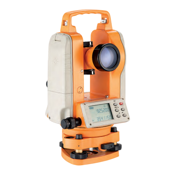
- Page 1 Users‘ manual Electronic Theodolite FET 420K / FET 405K...
-
Page 2: Table Of Contents
C ONTENTS 1) I mportant 2) U sage 3) F eatures (1) 4) F eatures (2) 5) D isplay indication 6) O perating panel 7) P reparation for measurement 8) P ower on 9) B attery indication 10) B attery replacement... -
Page 3: I Mportant
1 I MPORTANT! READ THIS BEFORE USING YOUR INSTRUMENT • Make a full check for the instrument before using it. Be sure that the instrument’s functions, p ower, original settings and revised parameters meet your requirements before you operate it. • To avoid direct sunlight to the instrument’s lens, never leave the instrument exposed to ex- t reme heat longer than necessary, or it could affect the instrument’s accuracy. • When mounting or dismounting the instrument to or from the tripod, hold the instrument by one h and, turn the central screw on the tripod by the other hand to prevent the instrument from f alling. If the instrument must be carried on the tripod, hold the instrument as vertically as p ossible. Never carry the instrument horizontally over your shoulder. Any long distance transport s hould be done with the instrument in the carrying case. • Put the instrument in the carrying case to avoid extrusion, crash and shock during the transpor- t ation. Shockproof cushion should be necessarily put inside the carrying case during the long d istance transportation. • Clean the dirt on the surface of the organic glass and plastic by floss or brush after using the i nstrument. Dry the instrument in time after use in the rain. • Do not use harsh chemicals to clean the surface of the organic glass and plastic components. A water dampened rag is all that is necessary. • Use absorbent cotton or lenses tissue to clean the exposed optical parts. Handkerchief, clothes o r other things like that are forbidden for cleaning. •... -
Page 4: F Eatures
3 F EATURES (1) 1) O ptical sight 2) O bjective lens 3) H orizontal clamp knob 4) H orizontal tangent screw 5) D isplay 6) O perating keys 7) T ripod base plate 8) C arrying handle 9) H andle screw 10 ) I nstrument center mark 11) P late vial... -
Page 5: D Isplay Indication
5 D ISPLAY INDICATION 1) Ht General value of repeated measurements 2 V Vertical angle 3) Number of repeated measurements 4) A VG Average of repeated measurements 5) H Right horizontal angle 6) H Left horizontal angle 7) T ILT Incline compensator function 8) F Optional function keys 9) G Angle unit GON 10) % Vertical slope % 11) R EP State of repeated measurement... -
Page 6: P Reparation For Measurement
7 P REPARATION FOR MEASUREMENT L evel and center the instrument precisely to ensure its best performance. a M ount the tripod F irstly place the tripod legs to a suitable position and tighten the locking device. b M ount the instrument A ttach the instrument to the tripod carefully, and then move the instrument by loosening c enter screw. Lock slightly the center screw on the tripod when the plummet is centered a bove the mark. c R oughly level the instrument with the circular vial 1 U se footscrew 1, 2 to move the air bubble in the circular vial so it is centered left to right. 2 U se footscrew 3 to move the air bubble to the center of the vial. d F ine tune level the instrument with the plate level 1 L oosen horizontal clamp knob. Turn the instrument to place the plate vial parallel with t he footscrew 1, 2. Center the bubble using these two footscrews. Attention: Turn the two f oot screws reversely when you adjust them. -
Page 7: P Ower On
A djust the plate level if the bubble is not centered in step 4 e C entering the instrument using the optical plummet A djust the eyepiece according to the observer’s eyesight, then move the instrument by l oosening center screw until the image of the sign on the ground centered in the circle of t he reticule. Move the instrument carefully in case it appears incline. f F inal levelling of the instrument L evel the instrument precisely in the similar way to step 4. Rotate the instrument to see if t he bubble in the plate vial is centered, then tighten the center screw. 8 P OWER ON a W hen pressing the button by 1 sec. audio tone sounds and after a test p eriod of about 2 seconds in which all segments are displayed instrument is r eady for use. b M ove telescope to activate vertical angle reading. c P ush V% button to show vertical angle “0” point. T arget “0”... -
Page 8: B Attery Indication
9 B ATTERY INDICATION T he battery symbol on the display shows the current battery state. Full power Effective Effective Low power but effective, replace the battery. Instrument will shut off automatically shortly. Replace batteries immediately. B attery operating time will vary depending on type, brand and quality of the battery. We s uggest always to secure for a 2nd standby battery set. F or any questions about replacing batteries, see chapter “battery replacement”. 1 0 B ATTERY REPLACEMENT a R emoving the battery P ush down the press button and remove the battery compartment. b B attery replacement P ush down the hook to pull cover board away from the battery compartment. R eplace the old batteries by new ones. Take care of correct polarity. S nap the battery cover back into place. c M ounting battery compartment S lip the projection on the bottom of the battery compartment into the slot. Push the press b utton on top of the battery compartment until it clicks into place. -
Page 9: A Ngle Measurement
1 1 A NGLE MEASUREMENT V ertical plate left/right observation “ Plate left” means the vertical plate is on the left side by the telescope when the observer faces t he eyepiece. “Plate right” means the opposite to the “plate left”. Taking the average reading of t he “plate left” and “plate right” as the observation value can effectively remove the correspon- d ing effect on the observer from the system errors in the instrument. Therefore, turn the teles- c ope 180° for the “plate right” observation after the accomplish of the “plate left” during the o bservation of the horizontal and vertical angle. T arget aim P oint the telescope at the brightness and focus the eyepiece until the crosshair can be seen c learly. (Turn the focusing knob in the direction facing the observer, then focus in reverse d irection.) A im at the target coarsely using the coarse aiming device. The definite space can be kept b etween the device and the observer when aiming coarsely. F ocus the target by turning the focusing knob on the telescope. A ttention: T he visual errors of the target and reticule crosshair will be created in the horizontal and vertical d irection if the telescope or the eyepiece are not focused precisely, which can result in the m easuring errors. Focus for the telescope and eyepiece should be necessary to remove the v isual errors. -
Page 10: M Easuring Horizontal And Vertical Angle (Hr, V Or Hl, V)
1 3 M EASURING HORIZONTAL AND VERTICAL ANGLE (HR, V or HL, V) H orizontal rightward turning increment and vertical angle measurement /HR, V) O PERATING PROCESS DISPLAY A im at target A using crosshair of the telescope. P ress 0SET key once to set reading of horizontal angle 0°00’ 00”. T urn instrument clockwise and aim at the second target B to get its h orizontal and vertical angle. 1 4 M ODE CONVERSION OF HORIZONTAL RIGHTWARD (HR) AND LEFTWARD (HL) T URNING INCREMENT O PERATING PROCESS DISPLAY A im at target “A” using crosshair of the telescope. P ress R/L key, transform horizontal angle mode HR into t he mode HL. M easuring by mode HL. R /L key is of no effect to the vertical angle. P ress R/L key again, transform mode HL into mode HR. -
Page 11: H Orizontal Angle Locked - Unlocked
1 5 H ORIZONTAL ANGLE LOCKED - UNLOCKED D uring the process of level observation, press HOLD key once to keep the measuring angle. A fter the horizontal angle held, the value of the horizontal angle on the display window blinks. T here is no change to the horizontal angle even if the instrument is rotated. When the direction a imed correctly, press HOLD key once again to unlock the holding state. The direction of the h orizontal angle the instrument currently aimed is just the angle locked before. O ERATING PROCESS DISPLAY T urn the tangent knob and place the required horizontal a ngle. P ress HOLD key once , hold and flicker the value of the h orizontal angle. A im at the target. P ress HOLD key, no blink and hold to the value of the h orizontal angle. H OLD key is of no effect to the vertical angle. -
Page 12: M Easurement Of Zenith Distance, Vertical Angle And Height Angle
1 6 MEASUREMENT OF ZENITH DISTANCE, VERTICAL ANGEL AND HEIGHT ANGLE T he vertical angle should be originally set according to the needs before the operation. Z ENITH DISTANCE I f choose 0° for the vertical angle as the zenith direction, the measured vertical angle V i s the zenith angle. Z ENITH DISTANCE V=(L+360°-R)/2 S PECIFICATON ERROR i=(L+R-360°)/2 V ERTICAL ANGLE I f choose 0° for the vertical angle in left direction, the measured vertical angle V is the v ertical angle. V ERTICAL ANGLE V=(L+180°-R)/2 S PECIFICATION ERROR i=(L+R-540°)/2 H EIGHT ANGLE I f choose 0° for the vertical angle in both left and right direction, the measured vertical a ngle V is the height angle. H EIGHT ANGLE V=(L+R)/2 S PECIFICATION ERROR i=(L–R)/2 A TTENTION: If SPECIFICATION ERROR |i|≥10“ inspect and adjust according to the i nstruction manual. S LOPE PERCENT MODE (slope angle measurement) M easuring in angle mode, the vertical angle could be transformed into percent of grade. -
Page 13: A Ngular Repeated Mesurement
1 7 ANGULAR REPEATED MEASUREMENT O PERATION PROCESS DISPLAY 1 P ress FUNC key. 2 P ress REP key to put the instrument in repeated mode. 3 A im at target A and press 0SET key once to set the first t arget reading 0°00’ 00”. 4 T urn the horizontal tangent knob to aim at the second t arget B. 5 P ress HOLD key to hold the horizontal angle and store in t he instrument. 6 T urn the horizontal tangent knob to aim at the target A a gain. Press R/L key to release the angle and keep the s tate. 7 T urn the horizontal tangent knob to aim at the target B a gain. -
Page 14: F Unction Setting
1 8 F UNCTION SETTING T he instrument supplies multi-functions for your option to meet different requires of m easuring configuration. I TEM INSTRUCTION PARAMETER SETTING 1 M inimum rea- Change between 10“ Setting 0 Setting 1 d ing and 20“ 10“ 20“ 2 Q uadrant Confirm every 90° Setting 0 Setting 1 s ignal tone by signal tone off 3 U nit of angle Change between DEG, Setting 0/DEG... -
Page 15: F Actory Settings
20 F ACTORY SETTINGS M inimum reading 10“ Q uadrant signal tone U nit of angle measurement 360° A utomatic shut-off V ertical angle measuring-mode zenith angle A utomatic compensation off D ata transmission 2 1 E RROR DISPLAY D ISPLAY ERROR CONTENT AND DISPOSAL B Vertical compensator out of compensating range. Level the instrument again. E 00 Collimate rotating too fast. Press 0SET key to set 0. If “E00” is shown again instrument needs to be repaired. -
Page 16: M Ount And Dismount Of The Base Plate
2 2 M OUNT AND DISMOUNT OF THE BASE PLATE L oosening or tightening turning handle can easily mount or dismount the instrument to or from t he base plate. D ismount T urn the fixed pull handle 180° counterclockwise. Hold the base plate by one hand, bring up t he instrument using the carrying handle by the other hand. M ount B ring up the instrument by hand and aim the orientation block at the orientation slot. Mount the i nstrument on the base plate carefully. Tighten the fixed pull handle on the base plate. 2 3 CHECK AND ADJUSMENT Adjustment instruction A djust the eyepiece and focus it precisely to avoid the visual errors before the observation t hrough telescope. A djustment should be carried out one by one according to the following steps because each s tep’s adjustment is based on its former one’s result. Disorder the steps will default the adjust- m ent. T ighten the screw after the adjustment! The strength applied should be suitable because o vertighten will damage the thread. A fter the adjustment repeat the inspection to make sure that the adjustment has been well d one. - Page 17 I nspect and adjust the circular vial I nspection I f the circular vial is centered correctly after levelling the instrument according to the long vial, t hen no further adjustment is necessary. If not, please proceed with the following adjustment. A djustment T here are three adjusting screws on the bottom of the circular vial. When adjusting, loosen the s crew opposite to the bubble’s moving direction (one or two), then tighten the rest screws a long the bubble’s moving direction to center the bubble. The tightening strength of these t hree screws should be coincided. Adjusting screw Circular The bottom part vial The telescope reticule I nspection M ount the instrument on the tripod and level it carefully. S et target point A 50 meters to the instrument, aim at point A by the stadia hairs. T urn the telescope and observe point A whether it moves along the vertical hair. I f point A moves along the vertical hair, that means the vertical hair is perpendicular to the h orizontal axis, then no further adjustment is necessary. A djustment is necessary if point A moves deviated from the vertical hair Fixing screw Adjusting screw...
- Page 18 Perpendicular degree of the visual axis to the horizontal axis I nspection S et two obvious targets as high as the instrument about 100 meters apart with the instrument i n their center point. L evel the instrument precisely and power it on. A im at target A using crosshair of the telescope plate-leftward. L oosen the vertical braking knob. Rotate the telescope around the horizontal axis 180° to aim i t at the opposite direction. A im at target B with the same distance to target A R otate the horizontal braking knob to turn the instrument 180°. A im at the target A, then lock the knob. R otate the vertical braking knob to turn the instrument 180°. Aim at target C. Target C s hould be superposed to target B. If not, adjustment is necessary. A djustment R emove the reticule cover between the eyepiece of the telescope a nd the focusing knob. S et up point D between point B and C. The distance of DC should b e a quarter of BC. Adjust the two adjusting screws to move the r eticule to have its cross aim at point D. R epeat above inspection and adjustment steps until B and C are s uperposed. A ssemble back the reticule cover to its original position.
- Page 19 Automatic compensation of the vertical axis T he instrument is equipped with the electronic incline sensor device, which can compensate t he vertical axis. C heck A fter mounting and levelling the instrument, coincide the point of the telescope with the line b etween the center of the instrument and its any level screw. Then tighten the horizontal b raking knob. S et zero for indication of the vertical plate after power-on. Tighten the vertical clamp knob and t he instrument displays the current value of the vertical angle the telescope pointed. T urn the footscrew in one direction till 10 mm (circle distance). The value of vertical angle a lso changes correspondingly till it disappears and the symbol “b” is shown, which means the i ncline of the instrument’s axis has exceeded out of the compensated range. When turning the l evelling screw in reverse, the instrument returns to display the vertical angle (repeat testing and o bserve the changes on the critical point), which means the compensation device works well. A djustment W hen the compensation doesn’t work well or works abnormally, send to the factory for repair.
- Page 20 Vertical plate angle specification ( “i” angle) and its 0 set C heck A fter mounting and levelling, power on the instrument. Aim the telescope at any clear target A to get the reading L, which is the upright angle plate leftward reading. T urn the telescope conversely and aim at target A again to get the reading R, which is the up- r ight angle plate rightward reading. I f upright angle is in the zenith angle mode, then i=(L+R - 360°) /2. I f upright angle is in the vertical angle mode, then i=(L+R - 180°)/2 or i=(L+R - 540°)/2 I f upright angle is in the height angle mode, then i=(L–R)/2 I f the specification errors |i|≥10”, 0 reset of the upright plate is necessary. A djustment O perating procedures Operation Display L evel the instrument accurately with the p late vial. P ower on the instrument, the vertical angle a nd horizontal angle are displayed after upright Rotate the telescope p asses zero position. P ress FUNC key once, and then press V/% key. FUNC R otate the instrument and precisely aim at the...
- Page 21 Check and adjust the optical plummet T o superpose the optical axis of the plummet and the vertical axis, adjustment for the plummet i s neccessary, otherwise the vertical axis will not be on the true anchor point when the aim b egins. I nspection M ount the instrument on the tripod and place a sheet of paper with a cross on it under the i nstrument. A fter adjusting the focus of the optical plummet, move the paper to center the cross of the c rosshair in the field of view. T urn the collimator 180º, observe the superposed degree of the center mark and the cross. I f the center mark of the optical plummet and the cross of the hair keep superposed when tur- n ing the collimator, adjustment is unnecessary. If not, adjust it. A djustment T urn counterclockwise and remove the adjusting screw cover between the optical centering d evice and the focusing knob. F ix the sheet of paper with the cross on it and mark the fallen point of the center mark each t ime when the instrument turns 90º, shown as the illustration: point A, B, C, D. L ine up points on the cross AC and BD to get the point of their intersection O. R egulate the four adjusting screws on the optical plummet with the adjusting pin to superpose t he center mark and point O. Other adjustment A djust the two levelling screws on the base plate if the screw loosens. The tightening strength s hould be suitable.
-
Page 22: T Echnical Specification
2 4 T ECHNICAL SPECIFICATIONS FET 420K FET405K T elescope: M agnification 30× 30 x C lear objective aperture 45 mm 45 mm S hortest focussing distance 1,4 m 1,4 m A ngle measurement: incremental incremental A ccuracy 4 mgon (20“) 1 mgon (5“) S hortest focussing distance 2 mgon (10“) 0,5 mgon (2“) C ompensator Automatic Automatic... -
Page 23: S Afety Instructions
2 7 S AFETY INSTRUCTIONS • Please follow up instructions given in operators’ manual. • Use instrument for measuring jobs only. • Do not open instrument housing. Repairs should be carried out by authorized workshops only. P lease contact your local dealer. • Do not remove warning labels or safety instructions. • Keep instrument away from children. • Do not use instrument in explosive environment. 2 8 S PECIFIC REASONS FOR ERRONEOUS MEASURING RESULTS • Measurements through glass or plastic windows; • dirty laser emitting windows. • After instrument has been dropped or hit. Please check accuracy. • Large fluctuation of temperature: If instrument will be used in cold areas after it has been s tored in warm areas (or the other way round) please wait some minutes before carrying out m easurements. 2 9 E LECTROMAGNETIC ACCEPTABILITY (EMC) •... -
Page 24: G Uarantee
T he manufacturer, or its representatives, assumes no responsibility for consequential damage, a nd loss of profits by any disaster (earthquake, storm, flood etc.), fire, accident, or an act of a t hird party and/or a usage in other than usual conditions. T he manufacturer, or its representatives, assumes no responsibility for any damage, and loss of p rofits due to a change of data, loss of data and interruption of business etc., caused by using t he product or an unusable product. T he manufacturer, or its representatives, assumes no responsibility for any damage, and loss of p rofits caused by usage other than explained in the users‘ manual. T he manufacturer, or its representatives, assumes no responsibility for damage caused by w rong movement or action due to connecting with other products. g eo-FENNEL GmbH K upferstraße 6 D -34225 Baunatal T el. +49 561 49 21 45 F ax +49 561 49 72 34 E mail: info@geo-fennel.de w ww.geo-fennel.de A ll instruments subject to technical changes. 08/2008...
Need help?
Do you have a question about the FET 420K and is the answer not in the manual?
Questions and answers