Table of Contents
Advertisement
Advertisement
Table of Contents

Related Manuals for geo-FENNEL FET 420K


Summary of Contents for geo-FENNEL FET 420K
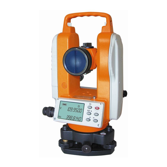
- Page 1 Operators’ Manual Electronic Theodolite FET 420K...
- Page 2 IMPORTANT! READ THIS BEFORE USING YOUR INSTRUMENT 1. Make a full check for the instrument before using it. Be sure that the instrument’ s functions, power, original settings and revised parameters meet your requires before you operate it. 2. To avoid direct sunlight to the instrument’ s lens, never leave the instrument exposed to extreme heat longer than necessary, or it could affect the instrument’...
-
Page 3: Table Of Contents
CONTENTS USAGE NOMENCLATURE and FUNCTIONS 1. Nomenclature 2. Display Marks 3. Operating keys PREPARATION BEFORE MEASUREMENT 1. Mounting to prepare for measurement 2. Power on 3. Battery state indication 4. Battery replacement ANGLE MEASUREMENT 1. Left/Right Observation 2. Target Aim 3. - Page 4 ANGLE MEASUREMENT 5. Horizontal Angle Locked----Unlocked (HOLD) 6. Measuring Zenith Distance, Vertical Angle and Height Angle 7. Grade Percent Mode (Grade Angle Measurement) 8. Repeating Angle Measurement OTHER FUNCTIONS 1. Measuring distance by crosshair of the telescope 2. Incline Correction Function 3.
- Page 5 The resolving power of horizontal and vertical angles can reach 10” . The precision of angle measurement can reach 20” . Electronic Digital Theodolite FET 420K can be widely used in 3-4 class national triangle control measurement, precise lead measurement,...
-
Page 6: Operating Keys
NOMENCLATURE AND FUNCTIONS Optical sight Objective lens Horizontal Clamp Knob Horizontal Tangent Screw Display Operating keys Tripod Base Plate Carrying Handle Handle Screw (10) Instrument Center Mark (11) Plate vial (12)Circular vial... - Page 7 Focusing Knob Optical plummet Communication Plug Footscrew Battery Compartment Telescopes Eyepiece Vertical Clamp Knob Vertical Tangent Screw Clamp of Tribrach...
-
Page 8: Display Marks
DISPLAY and DISPLAY MARKS DISPLAY INDICATIONS DISPLAY INDICATIONS TILT General value Incline compensator function repeated values Optional Function keys Vertical angle Angle unit GON Number repeated Vertical slope % measurements State repeated Average repeated measurement measurements Battery state indication Right horizontal angle Left horizontal angle... - Page 9 OPERATING PANEL and OPERATING KEYS FUNCTION FUNCTION FUNC Optional function keys Lighting switch for display window Repeated angle measurement HOLD Hold horizontal angle Vertical angle display Option of left/right horizontal angle Vertical angle/percent display 0SET 0SET for horizontal angle Power Switch Move cursor leftward Move cursor rightward Alter the number cursor indicated...
-
Page 10: Preparation Before Measurement
PREPARATION FOR MEASUREMENT 1. MOUNT INSTRUMENT and PREPARE FOR MEASUREMNET Level and center the instrument precisely to get the best performance. a. Mount tripod Firstly place the tripod legs to a suitable spot and tighten the locking device. b. Mount instrument Attach the instrument to the tripod carefully, then move instrument by loosening center screw. - Page 11 ? Return to the original position in step A. Rotate the instrument 180°. The plate vial is mounted correctly and the instrument is leveled nicely if the bubble is centered no matter the instrument is rotated in any direction. ? Please pay attention to the relations between the turning direction of the level screws and the moving direction of the bubble.
-
Page 12: Power On
2. FA POWER ON a. When pressing the button by 1 sec. audio tone sounds and after a test period of about 2 seconds in which all segments are displayed instrument is ready for use. b. Move telescope to activate vertical angle reading. -
Page 13: Battery State Indication
BATTERY STATE INDICATION The battery symbol on the display shows the current battery state. Full power Effective Effective Low power but effective, replace the battery Instrument will shut off automatically shortly. Replace batteries immediately. ? Battery operating time will vary depending on type and brand and quality of the battery. -
Page 14: Battery Replacement
4. BATTERY REPLACEMENT a. Removing the battery Push down the press button and remove the battery compartment. b. Battery replacement ? Push down the hook to pull cover board away from the battery compartment. ? Replace the old batteries by new ones. Take care of correct polarity. -
Page 15: Angle Measurement
ANGLE MEASUREMENT Vertical Plate left/right observation “ Plate left” means the vertical plate is on the left side by the telescope when the observer faces the eyepiece. “ Plate right ” means the opposite to the “ plate left” . Taking the average reading of t he “... -
Page 16: Horizontal Angle 0Set (0Set)
3. Horizontal angle 0set (0SET) OPERATING PROCESS DISPLAY Aim at target “ A” using crosshair of the telescope. ? Press 0SET key once to set reading of horizontal angle 0°00’ 00” ? 0SET key is only effective to the horizontal angle. ? Horizontal angle can be set “... - Page 17 4. 2 Mode conversion of horizontal rightward (HR) and leftward (HL) turning increment OPERATING PROCESS DISPLAY Aim at target “ A” using crosshair of the telescope. ? Press R/L key, transform horizontal angle mode HR into the mode HL. ? Measuring by mode HL. ? R/L key is of no effect to the vertical angle.
- Page 18 OERATING PROCESS DISPLAY ? Turn the tangent knob and place the required horizontal angle. ? Press HOLD key once , hold and flicker the value of the horizontal angle. ? Aim at the target. ? Press HOLD key, no blink and hold to the value of the horizontal angle HOLD key is of no effect to the vertical angle.
- Page 19 6. 3 HEIGHT ANGLE If choose 0°for the vertical angle in both left and right direction , the measured vertical angle V is the height angle. HEIGHT ANGLE V=(L+R)/2 SPECIFICATION ERROR i=(L– R)/2 ATTENTION: If SPECIFICATION ERROR |i|=10?, inspect and adjust according to the instruction manual.
- Page 20 ANGULAR REPEATED MEASUREMENT OPETATION PROCESS DISPLAY ? Press FUNC key Press key to put the instrument in repeated mode ? Aim at target A and press 0SET key once to set the first target reading 0°00’ 00” . ? Turn the horizontal tangent knob to aim at the second target B.
- Page 21 FUNCTION SETTING SETTING INSTRUCTION The instrument supply multi-functions for your option to meet different requires of measuring configuration. ITEM SETTING Step Item Instruction Parameter setting Setting 0 Setting 1 Minimum Change reading between 10” and 20” 20“ Setting 0 Setting 1 Quadrant Confirm every...
- Page 22 Setting methods Power on the instrument, press FUNC key, then press key. The instrument enters the state of the original setting mode, display as follows: To select the required parameter use v and w keys. To change to correct parameter use key.
- Page 23 ERROR DISPLAY DISPLAY ERROR CONTENT AND DISPOSAL Vertical compensator out of compensating range. Level the instrument again Collimate rotating too fast. Press 0SET key to set 0. If “ E00” is shown again instrument needs to be repaired. Telescope turning too fast, press V/% key to set 0 for the vertical plate specification.
- Page 24 MOUNT and DISMOUNT of THE BASE PLATE Loosening or tightening turning handle can easily mount or dismount the instrument to or from the base plate. DISMOUNT ? Turn the fixed pull handle 180 degrees counterclockwise. ? Hold the base plate by one hand, bring up the instrument using the carrying handle by the other hand.
- Page 25 Offset 1/2 ? Inspect and Adjust the Circular Vial Inspection If the circular vial is centered correctly after leveling the instrument according to the long vial, then no further adjustment is necessary. If not, please proceed with the following adjustment. Adjustment There are three adjusting screws on the bottom of the circular vial.
- Page 26 ? The Telescope Reticule Inspection ? Mount the instrument on the tripod and level it carefully. ? Set target point A 50 meters to the instrument, aim at point A by the stadia hairs. ? Turn the telescope and observe point A whether it moves along the vertical hair ? If point A moves along the vertical hair, that means the vertical hair is perpendicular to the horizontal axis, then no further adjustment is necessary.
- Page 27 ? Perpendicular Degree of the Visual Axis to the Horizontal Axis Inspection ? Set two obvious targets as high as the instrument about 100 meters apart with the instrument in their center point. Level the instrument precisely and power it on. ? Aim at target A using crosshair of the telescope plate-leftward.
- Page 28 Adjustment Remove the reticule cover between the eyepiece of the telescope and the focusing knob. Set up point D between point B and C. The distance of DC should be a quarter of BC. Adjust the two adjusting screws to move the reticule to have its cross aim at point D.
- Page 29 ? Vertical plate angle specification ( “ i” angle) and its 0 set Check ? After mounting and leveling, power on the instrument. Aim the telescope at any clear target A to get the reading L the vertical plate leftward. ? Turn the telescope and aim at target A again to get the reading R the vertical plate rightward.
- Page 30 ? Check and Adjust the optical plummet To superpose the optical axis of the plummet and the vertical axis, adjustment for the plummet is neccessary, otherwise the vertical axis will not be on the true anchor point when the aim begins. Inspection ? Mount the instrument on the tripod and place a sheet of paper with a cross on it under the instrument.
- Page 31 Technical Specifications Telescope Image erect Magnification 30× Objective aperture 45mm Resolving power 3’ ’ Field of view 1º30? Minimum focus 1.4m Stadia multiplied by constant Stadia plus constant Stadia precision =0.4%L Length 157mm Angle measurement Method Incremental Diameter of circle 71mm Minimum reading 10?/20? (2/5mgon)
- Page 32 Display LCD-Display 2 sides Data input and output Plug (one) RS232 Power supply Alkaline batteries 4 x 1.5 V AA Operating time 15 hrs Operating temperature - 20°~ + 45° Weight 4 kg 09-2004...
Need help?
Do you have a question about the FET 420K and is the answer not in the manual?
Questions and answers