
Related Manuals for geo-FENNEL FL 155H-G


Summary of Contents for geo-FENNEL FL 155H-G
- Page 1 DE | EN | FR FL 155H-G BEDIENUNGSANLEITUNG USER MANUAL MODE D‘EMPLOI www.geo-fennel.de www.geo-fennel.com www.geo-fennel.fr...
- Page 2 Sehr geehrter Kunde, vielen Dank für das Vertrauen, welches Sie uns beim Erwerb Ihres neuen geo-FENNEL-Gerätes ent- gegengebracht haben. Dieses hochwertige Qualitätsprodukt wurde mit größter Sorgfalt produziert und qualitätsgeprüft. Die beigefügte Anleitung wird Ihnen helfen, das Gerät sachgemäß zu bedienen. Bitte lesen Sie ins- besondere auch die Sicherheitshinweise vor der Inbetriebnahme aufmerksam durch.
- Page 3 FUNKTIONEN UND EIGENSCHAFTEN · Horizontaler 2-Achsen-Neigungslaser · Digitale Neigungseinstellung · Überwachte Neigung · Automatische TILT-Funktion · VWS-Funktion, kombiniert mit TILT-Funktion · Laserstrahl sektionsweise abschaltbar (Masking) · Beleuchtbares Display · 2-Wege-Funkfernbedienung · Abschaltbare Fernbedienfunktion · Li-Ion-Akkutechnik · Internationales Ladegerät mit Adapter für Zigarettenanzünder im Auto Technische Daten Selbstnivellierbereich ±...
- Page 4 STROMVERSORGUNG EINLEGEN DER BATTERIE Der Laser kann mit Li-Ion-Akku und alternativ mit handels- üblichen Alkalinebatterien betrieben werden. Li-Ion-Akku Der Laser ist mit einem wiederaufladbaren Li-Ion-Akkupack ausgestattet. Ladegerät mit Netz und Ladebuchse am Gerät verbinden. Der Ladezustand wird an der kleinen Lampe am Ladegerät angezeigt: Rotes Licht zeigt an, dass der Akku geladen wird.
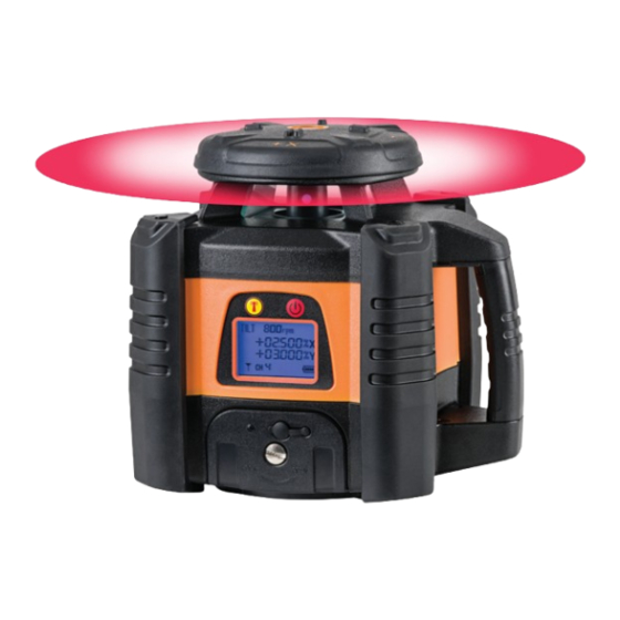
- Page 5 BATTERIEZUSTANDSANZEIGE Akku voll geladen Normale Akkuleistung Niedrige Akkuleistung Akku fast leer Akku leer BEDIENELEMENTE Laseraustrittsfenster Rotorkopf Tastatur Griff Display Batteriefach Batteriefachverschluss 5/8“-Gewinde...
- Page 6 BEDIENUNG Gerät auf einem Stativ befestigen. Gerät immer möglichst waagerecht aufstellen, damit die Selbstnivellierung des Gerätes einwandfrei arbeiten kann und der größtmögliche Neigungsbereich ausgeschöpft werden kann. BEDIENUNG AM GERÄT Kanalwahlschalter AN-/AUS-Schalter Channel setting button On/off button GERÄT EINSCHALTEN Gerät mit der An-/Aus-Taste einschalten.
- Page 7 KANALWAHL FERNBEDIENUNG Taste kurz drücken, um den Kanal der Fernbedienung zu wählen (nacheinander von CH2 zu CH9 und von A bis F = 14 Kanäle). Die Fernbedienung kann auf unterschiedlichen Kanälen betrieben werden, um zu vermeiden, dass sich mehrere Geräte auf einer Baustelle stören. BEDIENUNG MIT DER FERNBEDIENUNG FERNBEDIENUNG 1.
- Page 8 TILT-FUNKTION Mit dem Einschalten des Gerätes wird automatisch die TILT-Funktion aktiviert; „TILT“ blinkt während der Aktivierung im Display. Wenn sie abgeschlossen ist (nach ca. 90 Sek.), steht „TILT“ im Display (blinkt nicht mehr). Zum Ein- und Ausschalten der TILT-Funktion Taste drücken.
- Page 9 FERNBEDIENUNG Wenn die Fernbedienung eingeschaltet ist, zeigt das Display automatisch den zuletzt gewählten Kanal an. Mit der Taste können die Kanäle der Fernbedienung nacheinander von CH2 bis CH9 und von A bis F geschaltet werden. Die Fernbedienung hat 14 Kanäle. Wenn im Display angezeigt wird, zeigt dies an, dass die Fernbedienung keine Verbindung zum Gerät hat (Gerät ist zu weit entfernt, das Signal wird gestört, Kanäle von Gerät und Fernbedienung stimmen nicht überein).
- Page 10 PRÜFUNG DER NIVELLIERGENAUIGKEIT Der Anwender sollte sich vor jeder Anwendung von der Genauigkeit des Gerätes überzeugen. HORIZONTALPRÜFUNG Gerät auf einem Tisch o.ä. ca. 20 m von einer Wand entfernt aufstellen und Laserstrahl (X-Achse) auf die Wand projizieren. Lasertrahl auf der Wand mit Punkt A markieren und durch A eine Vertikallinie ziehen. Abstand H1 zwischen Geräteboden und Laserebene messen.
- Page 11 EMPFÄNGER FR 45 BEDIENELEMENTE 1. Libelle (2) 2. Display 3. Referenzmarke 4. Empfangsfenster 5. AN- / AUS-Schalter 6. Lautsprecher 7 . Batteriefach (Rückseite) 8. Ton an / aus 9. Genauigkeit grob / normal / fein 10. Beleuchtung an / aus 11.
- Page 12 GENAUIGKEITSEINSTELLUNG GROB/ NORMAL / FEIN Der FR 45 ist mit drei Genauigkeitsstufen ausgestattet. Zur Auswahl Taste (9) drücken: Genauigkeit grob ± 10 mm Displaysymbol: leeres Feld Genauigkeit normal ± 4 mm Displaysymbol: Genauigkeit fein ± 2 mm Displaysymbol: EINLEGEN DER BATTERIE •...
- Page 13 EMPFÄNGER FR 77-MM LIEFERUMFANG · Laser-Empfänger FR 77-MM · 4 x AA Alkalinebatterien · Halteklammer für Nivellierlatte · Spezialhalterung · Bedienungsanleitung Technische Daten Genauigkeit 3-stufig ± 2 mm / ± 5 mm / ± 9 mm Genauigkeit mm-Anzeige ± 1 mm Länge Empfangsfenster 125 mm Länge Empfangsbereich mm-Anzeige...
- Page 14 BEDIENELEMENTE Libelle Empfangsfeld Magnet 0SET-Taste (Offset) LED-Anzeige LCD-Anzeige Ton und Beleuchtung Einheiten umstellen ein / aus EIN-/AUS-Taste Empfangsgenauigkeit wählen Libelle Magnet Lautsprecher Arretierung für Halteklammer Gewinde für Halteklammer LED-Anzeige seitlich Markierung Nullposition LCD-Anzeige Rückseite LED-Anzeige hinten Batteriefachdeckel...
- Page 15 Anzeige Einheiten Vorzeichen +/- numerische Anzeige 0SET-Anzeige Anzeige Bezugshöhe Anzeige Genauigkeit Anzeige Beleuchtung Batteriezustandsanzeige Anzeige Ton EIN-/AUS-Taste Schaltet den Empfänger EIN /AUS Taste Empfangsgenauigkeit Auswahl der Empfangsgenauigkeit Taste Einheiten Auswahl der Einheiten Taste Ton / Beleuchtung Ein-/Ausschalten von Ton und Beleuchtung 0SET-Taste Setzen der relativen Null-Position...
- Page 16 STROMVERSORGUNG BATTERIE EINLEGEN / WECHSELN Batteriefachdeckel auf der Rückseite öffnen und 4 x AA Alkalinebatterien einlegen (auf Polarität achten). Batteriefachdeckel wieder schließen. Wenn das Gerät längere Zeit nicht benutzt wird, Batterien herausnehmen. Bei nachlassender Leistung Batterien rechtzeitig wechseln. BATTERIEZUSTANDSANZEIGE Das Display des FR 77-MM zeigt vier verschiedene Batteriezustände an. Sind die Batterien leer, schaltet das Gerät automatisch ab.
- Page 17 BEDIENUNG GERÄT EINSCHALTEN EIN/AUS-Taste einmal drücken, um das Gerät einzuschalten. Für ca. 0,5 Sek. leuchten alle Anzeigen auf (Bild links). Danach befindet sich das Gerät im Empfangsmodus (Anzeige siehe Bild rechts). EMPFANGSGENAUIGKEIT EINSTELLEN Gerät einschalten und mit der Taste „Empfangsgenauigkeit“ auswählen: fein, mittel, grob. Jetzt wird im Display das jeweilige Genauigkeitssymbol und der numerische Wert angezeigt.
- Page 18 DISPLAYBELEUCHTUNG EIN / AUS Gerät einschalten und zum Ein- oder Ausschalten der Hintergrundbeleuchtung Taste „ Ton/Beleuchtung“ gedrückt halten. UMSCHALTEN DER EINHEITEN Gerät einschalten und zum Auswählen der Einheiten Taste „UNITS“ so oft drücken, bis die gewünschte Einheit eingestellt ist. Das Symbol im Display zeigt die jeweilige Einstellung an. Millimeter Zentimeter Inch...
- Page 19 LASERSTRAHL EMPFANGEN Gerät einschalten und Einstellungen festlegen (z. B. Empfangsgenauigkeit fein, Ton laut). Zum Empfangen des Laserstrahls den Empfänger langsam auf und ab bewegen. Anzeige 1 Anzeige 2 Anzeige 3 LED „Laserstrahl hoch“ LED „Laserstrahl tief“ LED „0-Position“ leuchtet = leuchtet.
- Page 20 MM-ANZEIGE Wenn sich die Nullmarkierung des Empfängers z. B. 18 mm unterhalb des Laserstrahls befindet, wird dies durch den genauen Zahlenwert im Display angezeigt (siehe linke Grafik). weitere Beispiele Der Laserstrahl Der Laserstrahl ist Der Laserstrahl ist ist genau auf der 19 mm oberhalb 35 mm unterhalb Nullmarkierung...
- Page 21 ANWENDUNG Zum Empfangen des Laserstrahls die Libelle zentrieren, um die Genauigkeit zu erhöhen. Der Empfänger kann in Verbindung mit der Halteklammer aus dem Lieferumfang an einer Nivellierlatte befestigt werden. SPEZIALHALTERUNG Zur vielseitigen Befestigung z.B. am Schnurgerüst.
- Page 22 SICHERHEITSHINWEISE BESTIMMUNGSGEMÄSSE VERWENDUNG Das Gerät sendet einen sichtbaren Laserstrahl aus, um z.B. folgende Messaufgaben durchzuführen: Ermittlung von Höhen; rechten Winkeln, Ausrichtung von horizontalen und vertikalen Bezugsebenen sowie Lotpunkten (je nach Gerät). UMGANG UND PFLEGE Messinstrumente generell sorgsam behandeln. Nach Benutzung mit weichem Tuch reinigen (ggfs. Tuch in etwas Wasser tränken).
- Page 23 Sicherheitsmassnahmen eingesetzt werden. Das Auge ist bei zufälligem, kurzzei- tigem Hineinsehen in den Laserstrahl durch den Lidschlussreflex geschützt. Laserwarnschilder der Klasse 2 sind gut sichtbar am Gerät angebracht. www.geo-fennel.de GERM ANY Laser IEC 60825-1:2014 P ≤ 1 mW @ 635 - 670 nm...
- Page 24 Dear customer, Thank you for your confidence in us having purchased a geo-FENNEL instrument. This manual will help you to operate the instrument appropriately. Please read the manual carefully - particularly the safety instructions. A proper use only guarantees a longtime and reliable operation.
- Page 25 FEATURES · Horizontal Dual Grade Laser · Digital grade adjustment · Monitored grade · Automatic TILT function · VWS function combined with TILT function · Zonal control with electronic beam screen (masking) · Illuminated display · 2-Way RF remote control ·...
- Page 26 Both the standard Li-Ion battery or alkaline batteries can be used. Li-Ion battery pack The FL 155H-G comes with Li-Ion rechargeable battery pack. Connect the charger with the socket. A red light at the the charger indicates that the batteries are being charged.
- Page 27 BATTERY STATUS INDICATOR battery fully charged normal battery power low battery power very low battery power battery empty FEATURES Laser emitting window Rotating head Keypad Handle Display Battery case lock Battery case 5/8“ thread...
- Page 28 OPERATION Mount the laser onto a tripod.Chann Set up the instrument as upright as possible to allow the self-levelling system to function within the range and to make sure that the maximum slope range is available. OPERATION - INSTRUMENT KEYPAD Channel selection ON/OFF button Channel setting button...
- Page 29 REMOTE CONTROL CHANNEL Press this button short to select the remote control channel (ciruclarly from CH2 to CH 9 and from A to F = 14 channels). The channels of the remote can be changed in order to avoid that several units on one construction site disturb each other.
- Page 30 TILT FUNCTION Powering on the laser the TILT function will be activated automatically. „TILT“ is flashing during the activation procedure. When the activation is completed (after 90 sec approx.) „TILT“ is displayed permanently. Press button to switch this function on/off. When the TILT function is active: If the laser is disturbed, the rotation stopps and the laser beam and „TILT“...
- Page 31 REMOTE CONTROL When the remote control is powered on the display automatically shows the channel that was selected last. With the button the channels of the remote can be selected circularly from CH2 to CH9 and from A to F (14 channels are available). If the display shows the remote has no connection to the in- strument (the instrument is too far away, the connection is disturbed, the channels of the remote and the instrument are not the same, the remote is switched off).
- Page 32 ACCURACY CHECK The user is expected to carry out periodic checks of the product’s accuracy and general performance. HORIZONTAL PERFORMANCE CHECK Mount the instrument onto a tripod and set it up 20 m apart from a wall - the X axis showing to the wall. Switch on the instrument and let the laser complete the self-levelling process.
- Page 33 RECEIVER FR 45 FEATURES 1. Vial (2) 2. Display 3. Reference indicator 4. Receiving window 5. ON / OFF switch 6. Loudspeaker 7 . Battery compartment (back side) 8. Sound on / off 9. Accuracy coarse / normal / fine 10.
- Page 34 ACCURACY COARSE / NORMAL / FINE The FR 45 is equipped with three precision modes. They can be chosen by pressing button (9): Accuracy coarse ± 10 mm Symbol on display: without symbol Accuracy normal ± 4 mm Symbol on display: Accuracy fine ±...
- Page 35 RECEIVER FR 77-MM SUPPLIED WITH · Laser receiver FR 77-MM · 4 x AA alkaline batteries · Clamp for levelling rod · Special mount · User manual Technical Data 3 accuracy settings ± 2 mm / ± 5 mm / ± 9 mm mm-indication accuracy ±...
- Page 36 FEATURES Bubble vial Receiving window Magnetic strip 0SET button (Offset) LED indicators Front LCD Display Sound / illumination Units ON/OFF button Power ON/OFF Accuracy button Bubble vial Magnetic strip Loudspeaker Clamp alignment guide Clamp thread Side LED indicators 0-position (reference point) Rear LCD Display Rear LED indicatiors Battery compartment...
- Page 37 Units of measure Sign +/- Numerical indication 0SET symbol 0-position (reference point) Accuracy symbol Illumination symbol Battery status indicator Sound symbol ON/OFF button Power ON/OFF the receiver Accuracy button Select accuracy setting UNITS button Select units of measure Sound/illumination button Sound and/or illumination ON/OFF 0SET button Set a relative ZERO position...
- Page 38 POWER SUPPLY INSERT / REPLACE BATTERIES Open the battery compartment cover on the rear of the receiver and insert 4 x AA alkaline batteries Refer to the battery compartment diagram to ensure correct polarity. Close the battery compartment cover. Always remove the batteries if the receiver will not be used for a long period of time to avoid leakage. BATTERY STATUS INDICATOR The FR 77-MM front LCD display has four power status symbols.
- Page 39 OPERATION POWER ON Press the ON/OFF button once to power on the receiver. The LCD display will initialise taking about 0.5 seconds when all the display symbols are illuminated (see diagram, left). The receiver is now ready for use (see diagram, right). SELECT ACCURACY SETTING Power on the unit and select the receiving accuracy fine, normal or coarse by pressing the „accuracy button“...
- Page 40 SWITCH ON/OFF THE DISPLAY ILLUMINATION Power on the receiver and keep the button „Sound/illumination“ pressed until the illumination is on. SELECT THE UNITS Power on the receiver and press the „UNITS“ button sucessively until the required unit symbol appears in the display. Millimetre Centimetre Inch...
- Page 41 RECEIVE A LASER BEAM Power on the receiver and make all required settings (i. e. accuracy fine, sound high). Carefully move the receiver up and down to detect the laser beam. Indication 1 Indication 2 Indication 3 The laser beam is high The laser beam is low The LED „0-position“...
- Page 42 MM INDICATION If the reference level of the receiver is e. g. 18 mm below the laser beam this height difference will be displayed by an exact numerical value (see the left diagram). further examples The laser beam is The laser beam is The laser beam is exactly on-level.
- Page 43 APPLICATION Connect the clamp to the receiver for use with a laser pole, levelling staff or similar accessory. For optimum accuracy always level the bubble vials on the receiver before taking measurements. SPECIAL MOUNT To increase the versatility and scope of the receiver a special mount is provided (see illustrations).
- Page 44 SAFETY NOTES SPECIFIC REASONS FOR ERRONEOUS MEASURING RESULTS Measurements through glass or plastic windows; dirty laser emitting windows; after the instrument has been dropped or hit. Please check the accuracy. Large fluctuation of temperature: If the instrument will be used in cold areas after it has been stored in warm areas (or the other way round) please wait some minutes before carrying out measurements.
- Page 45 The instrument is a laser class 2 laser product according to DIN IEC 60825-1:2014. It is allowed to use the unit without further safety precautions. The www.geo-fennel.de GER MA NY eye protection is normally secured by aversion responses and the Laser blink reflex.
- Page 46 1. Livré comme suit 2. Alimentation 3. Description 4. Opération 5. Cellule 6. Consignes de sécurité LIVRÉ COMME SUIT · Laser horizontal à pente à deux axes FL 155H-G · Cellule de réception avec support · Télécommande · Accu Li-Ion ·...
- Page 47 CARACTÉRISTIQUES · Lasers double pente à deux axes · Rotatif automatique horizontal · Réglage digital de la pente · Inclinaison contrôlée · Fonction TILT automatique · Fonction VWS (protection contre les vibrations et le vent), combinée avec la fonction TILT ·...
- Page 48 ALIMENTATION Le laser fonctionne avec accu Li-lon. Comme solution de rechange, il peut fonctionner avec piles alcalines. Accu Li-Ion Le laser est équipé d’une batterie d’accu Li-lon. Relier le chargeur au réseau électrique et à la douille de charge. Le voyant de contrôle de charge fournit les indications sui- vantes: ROUGE = batterie d‘accumulateurs en charge...
- Page 49 AFFICHAGE DE L’ÉTAT DE CHARGE DE L’ACCUMULATEUR Accu plein charge Accu charge normal Accu faible Accu presque vide Accu vide DESCRIPTION Fenêtre de sortie du faisceau laser Tête de rotation Clavier Poignée Écran Logement de piles Fermeture du logement de piles Adaptateur 5/8“...
- Page 50 OPÉRATION Placez l‘appareil sur un trépied. Positionnez l‘appareil le plus plan que possible pour que l‘autonivellement puisse travailler parfaitement et l‘inclinaison maximum puisse être exploitée. OPÉRATION - CLAVIER DE L‘INSTRUMENT Choix de canal télécommande Touche MARCHE/ARRÊT Channel setting button On/off button METTRE L‘INSTRUMENT EN MARCHE Pressez le bouton pour mettre l’appareil en marche.
- Page 51 SÉLECTION DU CANAL DE LA TÉLÉCOMMANDE Pressez la touche pour sélectionner l’un des canaux de la télécommande (l’un après l’autre de CH2 à CH9 et de A à F = 14 canaux). La télécommande peut fonctionner sur différents canaux, afin d’éviter que plusieurs instruments ne puis- sent se brouiller par interférence sur le même chantier.
- Page 52 FONCTION TILT La mise en marche de l’instrument provoque l’activation automatique de la fonction TILT; „TILT“ clignote sur l’écran pendant la phase d’activation. Lorsque celle-ci est achevée (après env. 90 sec.), „TILT“ reste immobile sur l’écran (ne clignote plus). Pour activer ou désactiver la fonction TILT, pressez la touche Lorsque la fonction TILT est activée : Si l’instrument subit une modification de position, la rotation s’arrête, le faisceau laser et „TILT“...
- Page 53 TÉLÉCOMMANDE Lorsque la télécommande est activée, l’écran affiche automatiquement le canal qui a été choisi la dernière fois. La touche permet de sélectionner l’un après l’autre les canaux de CH2 à CH9 et de A à F. La télécommande est pourvue de 14 canaux. Lorsque l’écran affiche cela signifie que la télécom- mande n’est pas reliée à...
- Page 54 VÉRIFICATION DE LA PRÉCISION DE NIVELLEMENT L’utilisateur devrait s’assurer de la précision de l’instrument avant chaque utilisation. VERIFICATION EN PLAN HORIZONTAL Mettre en place l’instrument sur une table située à env. 20 m d’une paroi et projeter le faisceau laser (axe X) sur cette paroi.
- Page 55 CELLULE FR 45 DESCRIPTION 1. Nivelle (2) 2. Écran 3. Hauteur de référence 4. Fenêtre de réception 5. Bouton marche/arrêt 6. Haut-parleur 7 . Logement de piles 8. Son marche/arrêt 9. Précision fine / normale / grossière 10. Éclairage marche/arrêt 11.
- Page 56 RÉGLAGE DE LA PRÉCISION FINE / NORMALE / GROSSIÈRE Le FR 45 est équipé de trois niveaux de précision. Pour choisir, pressez bouton (9): Précision grossière ± 10 mm Symbole sur l‘écran: champ vide Précision normale ± 4 mm Symbole sur l‘écran: Précision fine ±...
- Page 57 CELLULE FR 77-MM LIVRÉ COMME SUIT · Cellule de réception FR 77-MM · 4 x AA piles alcalines · Support de cellule pour mire · Support spécial · Mode d‘emploi Données techniques 3-niveaux de précision ± 2 mm / ± 5 mm / ± 9 mm Indication de la précision en mm ±...
- Page 58 CARACTÉRISTIQUES Nivelle Fenêtre de réception Aimant Bouton définition du point 0 (Offset) Voyants lumi- Écran neux Son / éclairage Sélection des unités ON/OFF Bouton ON/OFF Sélection de précision Nivelle Aimant Haut-parleur Blocage du support Filetage du support Voyants lumineux du côté...
- Page 59 Unité sélectionnée Signe +/- Nombres Indication 0SET Indication du point de référence Indication du niveau de précision Symbole rétro-éclairage Indication du niveau Symbole du son de la batterie Bouton ON/OFF Allumer l‘appareil ON/OFF Bouton précision Sélection de la précision Bouton unité Sélection des unités Bouton Son/retro-éclairage Activer/désactiver son ou rétro-éclairage...
- Page 60 ALIMENTATION EN COURANT INSÉRER / ENLEVER LES PILES Ouvrez le couvercle du compartiment des piles sur le côté arrière du récepteur et insérez 4 piles alcali- nes AA (prendre soin de polarité). Fermez le couvercle du compartiment des piles. Retirez les piles si vous n‘utilisez pas le récepteur pendant une longue période. Si le niveau des piles devient faible, les piles doivent être échangées.
- Page 61 UTILISATION ALLUMER L ’ A PPAREIL Appuyez sur le bouton ON / OFF une fois pour allumer l‘appareil. Pendant environ 0,5 sec. tous les voyants sont allumés (voir l‘image de gauche). Ensuite, le récepteur est en mode de réception (voir l’image de droite). SÉLECTIONNER LE NIVEAU DE PRÉCISION Allumez l‘appareil et sélectionnez le niveau de précision de réception fine / normale / grossière avec le bouton „Sélection de précision“...
- Page 62 ACTIVER / DÉSACTIVER LE RÉTRO-ÉCLAIRAGE Allumez l‘appareil et maintenez le bouton „Son/rétro-éclairage“ enfoncé jusqu‘à ce que le rétro- éclairage soit allumé. SÉLECTION DES UNITÉS Allumez le récepteur et appuyez sur le bouton „unités“plusieurs fois jusqu‘à ce que l‘unité souhaitée s‘affiche à l‘écran. Millimètre Centimètre Inch...
- Page 63 RÉCEPTION DU FAISCEAU LASER Allumez le récepteur et après avoir fait tous les réglages nécessaires (c‘est à dire la précision, le son). Déplacez le récepteur soigneusement de haut en bas pour détecter le faisceau laser. Indication 1 Indication 2 Indication 3 Le voyant „monter vers le Le voyant „descendre vers le Le voyant „position 0“...
- Page 64 MM INDICATION Si le point 0 de référence du récepteur est par exemple de 18 mm au-dessous du faisceau laser, alors une valeur numérique exacte sera affichée (voir le graphique de gauche). Plusieurs exemples Le faisceau laser Le faisceau laser Le faisceau laser est exactement de est 19 mm au-...
- Page 65 APPLICATION Si nécessaire, monter le FR 77-MM sur son support. Ainsi la cellule peut être fixée sur des mires ou tout autre équipement. Afin d‘augmenter la précision de la cellule centrer la nivelle avant de détecter le faisceau laser. SUPPORT SPÉCIAL Pour différentes fixations, par exemple sur un échafaudage.
- Page 66 CONSIGNES DE SÉCURITÉ CIRCONSTANCES POUVANT FAUSSER LES RÉSULTATS DE MESURES Mesures effectuées à travers des plaques de verre ou de matière plastique; mesures effectuées à travers la fenêtre de sortie du faisceau laser lorsqu‘elle est sale. Mesures après que le niveau soit tombé ou ait subi un choc très fort. Mesures effectuées pendant de grandes différences de température - p.
- Page 67 Ce niveau correspond à la classe de sécurité des lasers 2, conformé- ment à la norme DIN EN 60825-1:2014. De ce fait, l’instrument peut être utilisé sans avoir recours à d’autres mesures de sécurité. Au www.geo-fennel.de GER MA NY Laser cas où...
- Page 68 GmbH Technische Änderungen vorbehalten. Kupferstraße 6 All instruments subject to technical changes. D-34225 Baunatal Sous réserve de modifications techniques. Tel. +49 561 / 49 21 45 +49 561 / 49 72 34 info@geo-fennel.de 10/2019 www.geo-fennel.de Precision by tradition.
Need help?
Do you have a question about the FL 155H-G and is the answer not in the manual?
Questions and answers