Advertisement
Quick Links
Advertisement

Related Manuals for geo-FENNEL FL 245HV +


Summary of Contents for geo-FENNEL FL 245HV +
- Page 1 DE | EN | FR FL 245HV + USER MANUAL www.geo-fennel.com...
- Page 2 Dear customer, Thank you for your confidence in us having purchased a geo-FENNEL instrument. This manual will help you to operate the instrument appropriately. Please read the manual carefully - particularly the safety instructions. A proper use only guarantees a longtime and reliable operation.
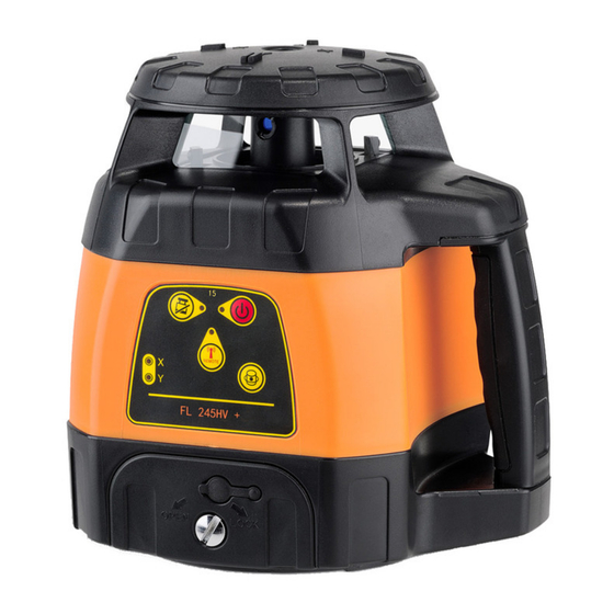
- Page 3 CHARACTERISTICS · Working range up to 1200 m diameter (depending on the receiver used) · Dust / water protection IP 65 for exterior application · Variable scanning and laser point mode · Permanent 90° plumb beam · Automatic TILT alarm function ·...
- Page 4 POWER SUPPLY Both the standard Li-Ion battery pack and alkaline batteries can be used. 1) Insert alkaline batteries into the alkaline battery box (ensure correct polarity) and fix the battery box into the instrument. 2) Fix the rechargeable battery box into the instrument. CHARGING THE BATTERY Connect the charger with the charging plug of the instrument and the power source.
- Page 5 OPERATION HORIZONTAL USE Set up the instrument on an even surface or mount it onto a tripod. After powering on the unit a flashing laser diode indicates that the automatic self-levelling procedure is working. The laser starts rotating when self-levelled. If not the laser was set up outside of its self- levelling range.
- Page 6 OPERATION - INSTRUMENT KEYPAD POWER ON/OFF (2) Power the laser on/off with button (2). If the red ON/ OFF LED (1) is illuminated the laser is powered on. First the laser dot is flashing, then the self-levelling procedure starts automatically; meanwhile the TILT LED (8) is flashing.
- Page 7 OPERATION WITH THE REMOTE CONTROL Slop SLOPE MODE (10) SLOPE SETTING (11) Slopes can be set up to ± 5° in X and Y direction. Slope adjustment axis Area scan Press button (10) to enter into this mode. To change between direction selection button or anti-clo X and Y axis press button (10) again.
- Page 8 APPLICATION...
- Page 9 RECEIVER FR 45 FEATURES 1. Vial (2) 2. Display 3. Reference indicator 4. Receiving window 5. ON / OFF switch 6. Loudspeaker 7 . Battery compartment (back side) 8. Sound on / off 9. Accuracy coarse / normal / fine 10.
- Page 10 ACCURACY COARSE / NORMAL / FINE The FR 45 is equipped with three precision modes. They can be chosen by pressing button (9): Accuracy coarse ± 10 mm Symbol on display: without symbol Accuracy normal ± 4 mm Symbol on display: Accuracy fine ±...
- Page 11 RECEIVER FR 77-MM SUPPLIED WITH · Laser receiver FR 77-MM · 4 x AA alkaline batteries · Clamp for levelling rod · Special mount · User manual Technical Data 3 accuracy settings ± 2 mm / ± 5 mm / ± 9 mm mm-indication accuracy ±...
- Page 12 FEATURES Bubble vial Receiving window Magnetic strip 0SET button (Offset) LED indicators Front LCD Display Sound / illumination Units ON/OFF button Power ON/OFF Accuracy button Bubble vial Magnetic strip Loudspeaker Clamp alignment guide Clamp thread Side LED indicators 0-position (reference point) Rear LCD Display Rear LED indicatiors Battery compartment...
- Page 13 Units of measure Sign +/- Numerical indication 0SET symbol 0-position (reference point) Accuracy symbol Illumination symbol Battery status indicator Sound symbol ON/OFF button Power ON/OFF the receiver Accuracy button Select accuracy setting UNITS button Select units of measure Sound/illumination button Sound and/or illumination ON/OFF 0SET button Set a relative ZERO position...
- Page 14 POWER SUPPLY INSERT / REPLACE BATTERIES Open the battery compartment cover on the rear of the receiver and insert 4 x AA alkaline batteries Refer to the battery compartment diagram to ensure correct polarity. Close the battery compartment cover. Always remove the batteries if the receiver will not be used for a long period of time to avoid leakage. BATTERY STATUS INDICATOR The FR 77-MM front LCD display has four power status symbols.
- Page 15 OPERATION POWER ON Press the ON/OFF button once to power on the receiver. The LCD display will initialise taking about 0.5 seconds when all the display symbols are illuminated (see diagram, left). The receiver is now ready for use (see diagram, right). SELECT ACCURACY SETTING Power on the unit and select the receiving accuracy fine, normal or coarse by pressing the „accuracy button“...
- Page 16 SWITCH ON/OFF THE DISPLAY ILLUMINATION Power on the receiver and keep the button „Sound/illumination“ pressed until the illumination is on. SELECT THE UNITS Power on the receiver and press the „UNITS“ button sucessively until the required unit symbol appears in the display. Millimetre Centimetre Inch...
- Page 17 RECEIVE A LASER BEAM Power on the receiver and make all required settings (i. e. accuracy fine, sound high). Carefully move the receiver up and down to detect the laser beam. Indication 1 Indication 2 Indication 3 The laser beam is high The laser beam is low The LED „0-position“...
- Page 18 MM INDICATION If the reference level of the receiver is e. g. 18 mm below the laser beam this height difference will be displayed by an exact numerical value (see the left diagram). further examples The laser beam is The laser beam is The laser beam is exactly on-level.
- Page 19 APPLICATION Connect the clamp to the receiver for use with a laser pole, levelling staff or similar accessory. For optimum accuracy always level the bubble vials on the receiver before taking measurements. SPECIAL MOUNT To increase the versatility and scope of the receiver a special mount is provided (see illustrations).
- Page 20 SAFETY NOTES SPECIFIC REASONS FOR ERRONEOUS MEASURING RESULTS Measurements through glass or plastic windows; dirty laser emitting windows; after the instrument has been dropped or hit. Please check the accuracy. Large fluctuation of temperature: If the instrument will be used in cold areas after it has been stored in warm areas (or the other way round) please wait some minutes before carrying out measurements.
- Page 21 It is allowed to use the unit without further safety precautions. The eye protection is normally secured by aversion responses and the blink reflex. The laser instrument is marked with class 2 warning labels. www.geo-fennel.de G ERMAN Y Laser IEC 60825-1:2014 P ≤...
- Page 22 GmbH Technische Änderungen vorbehalten. Kupferstraße 6 All instruments subject to technical changes. D-34225 Baunatal Sous réserve de modifications techniques. Tel. +49 561 / 49 21 45 +49 561 / 49 72 34 info@geo-fennel.de 10/2019 www.geo-fennel.de Precision by tradition.
Need help?
Do you have a question about the FL 245HV + and is the answer not in the manual?
Questions and answers