Table of Contents
Advertisement
Quick Links
Advertisement
Table of Contents

Subscribe to Our Youtube Channel
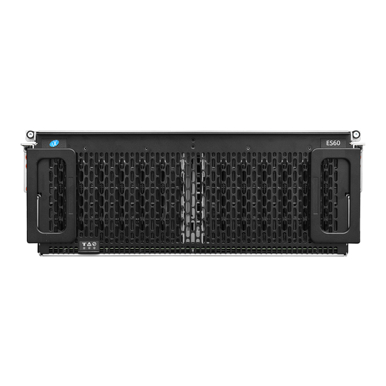
Summary of Contents for TrueNAS ES60 Gen 2
- Page 1 TrueNAS ES60 Gen 2 Racking Guide ® v.24031...
- Page 2 Introduction This document guides you through racking your shelf and connecting it to a TrueNAS storage array. See the back page of this document for guidance on where to access in-depth product information and setup recommendations. The ES60 requires a Phillips screwdriver and a T15 Torx screwdriver to install in a rack. We also recommend using a level to install the rails.
- Page 3 1 Remove Chassis Rail from Rack Rail Extend the innermost chassis rail until you expose the metal safety catch. Push the safety catch in and pull the chassis rail out until it is free from the rack rail. Repeat the process for the other rail. Press Left and Right Chassis Rails Rack Rail...
- Page 4 2 Install the Chassis Rail on the System Fit the rail keyholes over the mounting pegs on the chassis and slide the rail toward the back of the chassis until it locks. Use two low-profile M4x4 screws to secure the rail to the chassis. Repeat for the second chassis rail. Page 3 v.
- Page 5 3 Install the Rack Rail in the Rack The front rail pins mount to the 4U bottom-most attach points, and the back rail pins mount one hole above the 4U bottom-most attach points. The rails have left-side “L” and right-side “R” stamps. Install the front of the rail first.
- Page 6 4 Install Cover Retention Hardware At the front rack post, place a cage nut in the topmost rack mounting hole of the reserved 4U You can optionally place more cage nuts two, three, and five rack mounting holes down from the first one to lock the entire system to the rack later.
- Page 7 Place the left Cover Retention Bracket over the rail and align it with the mounting holes on the rear of the rack rail. The groove in the bracket must face toward the inside of the rack. Tighten the top two thumbscrews on the screwplate to secure the bracket to the rear of the rack rail. Use the same method to install the second alignment bracket to the other rail.
- Page 8 5 Extend the Middle Rails Slide the middle rack rails out until they click and lock. Ensure the bearing sleeve is also as far forward as possible. Page 7 v. 24031...
-
Page 9: Install The System In The Rack
6 Install the System in the Rack Team-lift the system and align the chassis rails with the rack rails, then slide them in and push the system into the rack until the metal safeties click and lock. Press the metal safety catches on each chassis rail against the chassis and gently push the chassis into the rack until the chassis latches lock into the latch plates. - Page 10 7 Install the Cable Management Brace At the back of the system, insert the brace pivot pin into the top bracket on the right rail. Swing the left side of the brace to the top bracket on the left rail and tighten the thumbscrew to secure the brace to the brace brackets.
- Page 11 8 Install the Lower Cable Management Arm (CMA) Starting with the left side, push the post onto the left bracket. On the right side, push the inner post onto the inner bracket, then push the outer post onto the outer bracket. The CMA posts click and lock when installed correctly.
- Page 12 9 Install the Upper Cable Management Arm (CMA) Starting with the right side, push the post onto the right bracket. On the left side, push the inner post onto the inner bracket, then push the outer post onto the outer bracket. The CMA posts click and lock when installed correctly.
-
Page 13: Install Cables
10 Install Cables Open the top CMA by pushing the blue release on the right CMA post and pulling it away from the bracket. Then, swing the top CMA out to the left. Open the bottom CMA by pushing the blue release on the left CMA post and pulling it away from the bracket. Then, swing the top CMA out to the right. - Page 14 Line the SAS3 cable connector up with the SAS port on the back of the system. Ensure the blue tab on the SAS cable is on top. Gently push the connector into the port until it clicks. For more information on SAS configuration, see the ES60 Gen 2 User Manual (https://www.truenas.com/docs/files/ ES60Gen2PUM.pdf).
-
Page 15: Install Drives
11 Install Drives Pull the latch handles to free the ES60 from the rack, then pull the ES60 out until it locks into the service position. Retrieve a drive assembly (drives and clips come pre-installed) and point the arrow on the clip towards the front of the ES60. -
Page 16: Boot The System
Plug the power cables into PDU outlets and wait for the ES60 to boot up. After booting, the ES60 automatically pairs with the TrueNAS system it is connected to. You can access ES60 hardware details through the TrueNAS UI. Note - Voltage Requirements The ES60 requires power from a 200V to 240V power distribution unit (PDU).


Need help?
Do you have a question about the ES60 Gen 2 and is the answer not in the manual?
Questions and answers