Table of Contents
Advertisement
Quick Links
Advertisement
Table of Contents

Subscribe to Our Youtube Channel
Related Manuals for TrueNAS ES102


Summary of Contents for TrueNAS ES102
- Page 1 TrueNAS ES102 Expansion Shelf ® Basic Setup Guide Version 1.04...
-
Page 2: Table Of Contents
............... . . 1.2 Become Familiar with the ES102 ... -
Page 3: Unpacking The Unit
1 Unpacking the Unit TrueNAS units are carefully packed and shipped with trusted carriers to arrive in perfect condition. If there is any shipping damage or any parts are missing, please take photos and contact iXsystems Support immediately at support@ixsystems.com or 1-855-GREP4-iX (1-855-473-7449) or 1-408-943-4100. -
Page 4: Become Familiar With The Es102
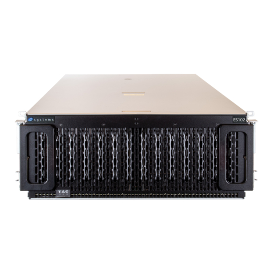
1.2 Become Familiar with the ES102 Indicators on the front panel show identification and status. The fault indicator is on during the initial power-on self- test (POST) or when the TrueNAS software has issued an alert. These indicators are also on the back panel. Name... -
Page 5: Prerequisites
You will need at least 37.5” (952.5mm) empty space in front of a racked ES102 to fully extend the enclosure to ac- cess all drive bays. Due to the weight of the enclosure, this can be a tipping hazard for the rack. Be sure to follow all tipping prevention instructions recommended by your rack provider before installing the ES102. -
Page 6: Rack Requirements
2.3 Rack Requirements At minimum, the ES102 requires 4U of space in a EIA-310 compliant rack that is 47.24” (1200mm) deep, from frame to frame. The vertical rack rails need to be spaced between 31.5” - 36.2” (800mm - 920mm) apart to properly install the ES102 rails. -
Page 7: Es102 Rail Installation Procedures
ES102. Then, fit the rack rails inside the rack. Next, install the additional components to secure the ES102 drive cov- er and latch the unit in the rack. Finally, you can reattach the ES102 to the rack rails and install it in the rack. -
Page 8: Rack Rails
3.2 Rack Rails The ES102 occupies 4U of rack space. The front rail pins mount to the 4U’s bottom-most attach points, and the back rail pins mount to one space above the 4U’s bottom-most attach points. The rails are stamped for left side (L) and right side (R) of the rack, according to your perspective when facing the rack. -
Page 9: Cover Retention
Use the same method to install the second alignment bracket to the other rail. Make sure the grooves on top of both brackets point inside the rack. The ES102 cover slides into the grooves when it is pushed into the rack. -
Page 10: Latch Plates
5 Latch Plates The latch plates attach to the front of the rack rails. They secure the rails to the rack and hold the enclosure in place when fully inserted in the rack. Align the plate over the three holds between the rack rail front mounting pins. The flange must point to the outside of the rack. -
Page 11: Mount The Unit In The Rack
(2). Caution: Do not use the front handles to lift the ES102! The handles are only for unlatching and sliding the enclo- sure after attaching it to the rack rails. They cannot support the system’s weight. Lift the ES102, align the attached cabinet rails with the middle rack rails, and push the ES102 into the rack rails until it stops. -
Page 12: Attach Cover Retention Screws
6.2 Shipping Screws If you will be installing the ES102 in a rack for shipping purposes, install four more M5 cage nuts in holes 3-6 of the 4U space. These will receive the M5 x 12mm T15 Flat Head Torx screws that secure the enclosure to the rack with the shipping bracket. -
Page 13: Es102 Cable Management Arms
You need the included Cable Management Arms (CMA) to ensure the ES102 remains properly cabled while sliding out of the rack. There are two CMAs included with the ES102 that attach to the rear of the enclosure in an Upper (U) Lower (L) configuration. -
Page 14: Install Upper Cable Management Arm
Before installing any drives in the ES102 or routing any cables through the CMAs, test the installation by unlatching the enclosure and sliding it forward until it clicks into place. The CMAs will fully extend behind the ES102, and the cover will remain in place, exposing the drive and component bay. -
Page 15: Drive Installation
For proper airflow, be sure to follow this drive installation order: Starting with the row at the back of the ES102 drive bay, install the drives from left to right. When that row is full, move to the next row forward and proceed to fill the enclosure from left to right, back to front. -
Page 16: Drive Led Indicators
8.3 Drive LED Indicators There is a single amber LED on each drive bay. The LED indicates different drive states: • Drive Insertion: Amber Light - Solid Note: LED stays in this state until the shelf is closed • Normal Behavior: No light. •... -
Page 17: Cabling
Do not plug the power cords into a power outlet yet. Start by connecting cables to the various ports on the back of the ES102 and routing through the cable management arms. Make sure to leave enough flex in the cables so that they don’t pull out of place when the enclosure slides out of the rack. -
Page 18: Sas Cables
9.2 SAS Cables ES102 systems are compatible with the M60 and R50 Unified Storage Arrays. Typical SAS cable connections for two ES102s to either system are shown here. To set up SAS between your TrueNAS system and Expansion Shelves, cable the first port on the first TrueNAS Controller to the first port on the first Expansion Shelf Controller. - Page 19 9.2.2 M60 M60 with a single ES102 Expansion Shelf M60 with three ES102 Expansion Shelves. The M60 can support up to 12 total Expansion Shelves with the use of additional SAS cards. Support: 1-855-473-7449 or 1-408-943-4100 Page 17 Email: support@ixsystems.com...
-
Page 20: Cable Routing
Return to the starting position and adjust the cables to allow more flex or avoid pinching. If the TrueNAS system is already on, you can turn on the ES102 any time by plugging both power cords into PDU outlets and waiting two minutes for the drives to start. -
Page 21: Additional Resources
TrueNAS web interface or go directly to: https://www.truenas.com/docs/ Additional hardware guides and articles are in the Documentation Hub’s Hardware section: https://www.truenas.com/docs/hardware/ The TrueNAS Community forums provide opportunities to interact with other TrueNAS users and discuss their con- figurations: https://www.truenas.com/community/ 10.1 Contacting iXsystems... - Page 22 Notes: Support: 1-855-473-7449 or 1-408-943-4100 Page 20 Email: support@ixsystems.com...
- Page 23 Notes: Support: 1-855-473-7449 or 1-408-943-4100 Page 21 Email: support@ixsystems.com...
- Page 24 Notes: Support: 1-855-473-7449 or 1-408-943-4100 Page 22 Email: support@ixsystems.com...
Need help?
Do you have a question about the ES102 and is the answer not in the manual?
Questions and answers