Table of Contents
Advertisement
Quick Links
Advertisement
Table of Contents

Subscribe to Our Youtube Channel
Related Manuals for TrueNAS R Series


Summary of Contents for TrueNAS R Series
- Page 1 TrueNAS R-Series Basic Setup Guide ® Version 1.32...
-
Page 2: Table Of Contents
� � � � � � � � � � � � � � � � � � � � � � � � � � � � � � � � � � � � � � � � � � � � � � � � � � � � � � � � � � � � � � � � � � � � � � � � � � � � � � � � � � � � � � � � � � � � � � � � � � � � � � � 12 Access the TrueNAS Web Interface ... -
Page 3: Introduction
1 Introduction TrueNAS R-Series systems are hard disk, hybrid, and all-flash storage arrays in 1U, 2U, and 4U configurations. You will receive the system and all installation components carefully packed and ready for installation� The packed items vary by what you purchased�... -
Page 4: R10 Components
Please locate and record the hardware serial numbers on the back of each chassis for quick reference� Carefully unpack the shipping boxes and locate these components: The R10 is a 1U All-Flash Storage Array with 16 SSD bays, redundant power supplies, and one TrueNAS controller. R10 All-Flash Storage Array... -
Page 5: 2�1 Front Ports And Indicators
2.1 Front Ports and Indicators The R10 front panel has buttons for system ID and power, a USB 2.0 port, and lights for network and disk activity. Light / Button Color and Indication Blue: Locate ID Active N/A: Reset Button Amber: Link Active Blue (Blinking): Disk Activity USB 2.0... -
Page 6: R20 Components
The R20 is a 2U Hybrid Storage Array that has 12 3.5” drive bays and 2 SSD drive bays, redundant power supplies, and a single TrueNAS controller. You will find these items when opening the R20 packaging: R20 Hybrid Storage Array... -
Page 7: 3�1 Front Ports And Indicators
USB 3.0 port. The fault indicator is on during the initial power-on self-test (POST) and turns off during normal operation. It turns on if the TrueNAS software issues an alert� Light / Button Color and Indication... - Page 8 R20B Rear Components and Ports The back panel has redundant power supplies, two SSD SATA Cache bays, and various connection ports� Power Supply 2 SATA PCIe Slots Cache Power Supply 1 OOBM Ethernet 10Gb RJ-45 USB 2.0 USB 3.0 Serial Port Port Not pictured: Serial number and IPMI password stickers are on the back of the chassis underneath the USB ports.
-
Page 9: R40 Components
4 R40 Components The R40 is a 2U All-Flash Storage Array that has 48 SSD drive bays, redundant power supplies, and a single TrueNAS controller. You will find these items when opening the R40 packaging: R40 All-Flash Storage Array Locking Bezel... -
Page 10: 4�1 Front Ports And Indicators
USB 3.0 port. The fault indicator is on during the initial power-on self-test (POST) and turns off during normal operation. It turns on if the TrueNAS software issues an alert� Light / Button Color and Indication... -
Page 11: Rack The R10, R20, Or R40
5 Rack the R10, R20, or R40 The R10, R20, and R40 share the same rail kit and racking process. Each system has slightly different dimensions, so we recommend double-checking the system’s rack rail placement� All three require an EIA-310 compliant rack� To properly install the rack rails, the front and rear vertical rack posts must be between 23”... -
Page 12: 5�2 Install Rack Rails
5.2 Install Rack Rails Before installing the rack rail, make sure the rack has enough space for the system. The R10 needs 1U of space for both the system and rack rails. The R20 and R40 needs 2U of space with the rack rails installed into the bottom 1U. Align a rack rail with the end stamped “FRONT”... -
Page 13: Install Or Replace Drives
6 Install or Replace Drives R-Series systems share many of the same drive trays� The general drive install and tray insertion procedures for each type of drive tray are described here: 6.1 Solid State Drives (R10, R20, R40) Placing locked SED drives in the R20 rear bays may cause the R20 to hang on boot indefinitely. We recommend not using SED drives with the R20 until we resolve the issue�... -
Page 14: 6�2 Hard Disk Drives (R20)
6.2 Hard Disk Drives (R20) To remove a hard drive tray, press the locking arm release at the right side of the tray front� Swing the arm out until it completely stops, then pull the tray free from the system� To remove a drive, push the side attached to the flexible pegs from underneath the tray, then lift the drive out. -
Page 15: Attach Bezel (R20 And R40)
7 Attach Bezel (R20 and R40) The R20 and R40 include an optional bezel you lock to prevent unauthorized access to the primary drive trays� Align the right side of the bezel with the attach points on the right ear and push the left side of the bezel into the attach points on the left ear until it clicks into place�... -
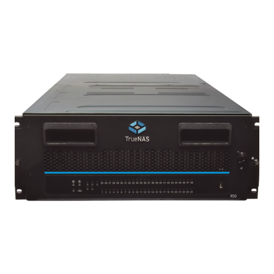
Page 16: R50 Components
The R50 is a 4U Hybrid Storage Array that has 48 3.5” and three 2.5” NVMe drive bays, redundant power supplies, and a single TrueNAS controller. You will find these items when opening the R50 packaging: R50 Hybrid Storage Array... - Page 17 The R50 front panel has buttons and indicators to help control the system. It also has one USB 2.0 port. The fault indicator is on during the initial power-on self-test (POST) and turns off during normal operation. It turns on if the TrueNAS software issues an alert� Disk Status LEDs USB 2.0...
- Page 18 R50B Rear Components and Ports Fan 1 Fan 2 Fan 3 NVMe Drives NVMe PCIe Slots Power Supply 2 Power Supply 1 OOBM Ethernet 10Gb RJ-45 USB 2.0 USB 3.0 Serial Port Port Support: 855-473-7449 or 1-408-943-4100 Page 16 Email: support@ixsystems.com...
-
Page 19: Rack The R50
9 Rack the R50 The R50 requires 4U of rack space in an EIA-310-compliant rack. The temporary assist rails require another 1U of rack space underneath the R50� The front and rear rack posts can have a four-inch (101�6mm) tolerance in four different depth configurations. -
Page 20: 9�4 Adjust Rail Sleeve
9.4 Adjust Rail Sleeve The rail sleeve uses position 2 by default� To adjust it, remove the 12 screws (yellow circles) and move the sleeve to the position that accommodates your rack depth (see table)� Pos. 1 Pos. 3 Pos. 4 Position Depth w/ Standard Ears Depth with 40mm Optional Extended Ears... - Page 21 9.6 Mount the R50 in the Rack Two people should lift the R50� Set the system onto the assist rails and align the rail sleeves with the rails� Slide the system forward until it is flush with the front of the rack. Use four M5 screws to secure the system to the rack.
-
Page 22: Install Drives
10 Install Drives The R50 drive drawer sits on internal rails and slides out of the system� Hard drives install into the drawer without drive trays� The NVMe drives are on the back of the system, and use removable trays to mount drives in the system� 10.1 Open the Drive Drawer Unlock the front and loosen the captive thumbscrews, then use the handles to pull the drawer out. -
Page 23: 10�3 Close The Drive Drawer
10.3 Close the Drive Drawer Pull the blue release catches on each rail toward you, then push the drawer into the system� To secure the drive bay and prevent it from accidentally opening, tighten the captive thumbscrews on the front of the system. -
Page 24: 10�4 Access Nvme Trays
10.4 Access NVMe Trays NVMe drives are hot-swappable, but the R50 won’t add the drive until after a power cycle� R50 NVMe drive bays are located behind a case fan on the back of the system� To remove the fan, rotate the handle downward, push down on the retention tab (1), and pull the fan free of the system (2)�... -
Page 25: Connect R-Series Cables
Out of Band Management port and a monitor and keyboard for the first boot so you can configure the system and view the initial TrueNAS web interface IP address� After connecting all other ports, plug in both power cables� Each system has retention clips that prevent accidentally unplugging the system�... -
Page 26: Access The Truenas Web Interface
12 Access the TrueNAS Web Interface Powering on the system and allowing it to boot to the system console will display the IP address of the TrueNAS R-Series graphical web interface, 192.168.100.231 in this example: The web user interface is at: http://192.168.100.231... -
Page 27: Additional Resources
TrueNAS web interface or go directly to: https://www�truenas�com/docs/ Additional hardware guides and articles are in the Documentation Hub’s Hardware section: https://www�truenas�com/docs/hardware/ The TrueNAS Community forums provide opportunities to interact with other TrueNAS users and discuss their con- figurations: https://www�truenas�com/community/ 14 Contacting iXsystems... - Page 28 Notes: Support: 855-473-7449 or 1-408-943-4100 Page 26 Email: support@ixsystems.com...
Need help?
Do you have a question about the R Series and is the answer not in the manual?
Questions and answers