Table of Contents
Advertisement
Quick Links
Advertisement
Table of Contents

Subscribe to Our Youtube Channel
Related Manuals for TrueNAS ES102


Summary of Contents for TrueNAS ES102
- Page 1 TrueNAS ES102 Expansion Shelf ® Basic Setup Guide Version 1.01...
-
Page 2: Table Of Contents
............... . . 1.2 Become Familiar with the ES102 ... -
Page 3: Unpacking The Unit
1 Unpacking the Unit TrueNAS units are carefully packed and shipped with trusted carriers to arrive in perfect condition. If there is any shipping damage or any parts are missing, please take photos and contact iXsystems Support immediately at sup- port@ixsystems.com... -
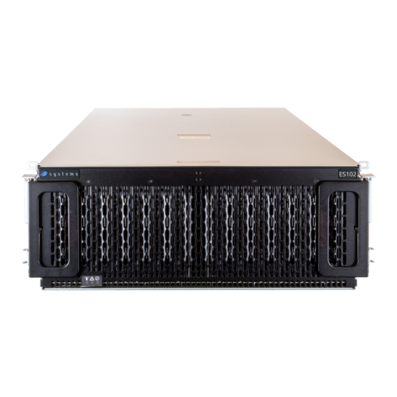
Page 4: Become Familiar With The Es102
Indicators on the front panel show identification and status. The fault indicator is on during the initial power-on self- test (POST) or when the TrueNAS software has issued an alert. These indicators are duplicated on the back panel. The ES102 has two expansion controllers in a side-by-side configuration. -
Page 5: Prerequisites
You will need at least 37.5” (952.5mm) empty space in front of a racked ES102 to fully extend the enclosure to ac- cess all drive bays. Due to the weight of the enclosure, this can be a tipping hazard for the rack. Be sure to follow all tipping prevention instructions recommended by your rack provider before installing the ES102. -
Page 6: Rack Requirements
The vertical rack rails need to be spaced between 31.5” - 36.2” (800mm - 920mm) apart to properly install the ES102 rails. It is recommended to adjust the front vertical rack rails to be as close to the front of the rack as possible to prevent the cable management arms (CMAs) from protruding from the back of the rack. -
Page 7: Rack Rails
3.2 Rack Rails The ES102 occupies 4U of rack space. The front rail pins are mounted to the bottom-most attach points of this 4U and back rail pins are mounted to one space above the bottom-most attach points of the 4U. The rails are stamped for left side (L) and right side (R) of the rack, according to your perspective when facing the rack. -
Page 8: Cover Retention
Use the same procedure to install the second alignment brack to the other rail. Make sure that the grooves on the top of both brackets are pointed inside the rack. The ES102 cover will slide into these grooves when it is pushed into the rack. -
Page 9: Mount The Unit In The Rack
They cannot support the weight of the system. Lift the ES102, align the attached cabinet rails with the middle rack rails, and push the ES102 into the rack rails until it stops. -
Page 10: Attach Cover Retention Screws
6.1 Attach Cover Retention Screws To hold the ES102 cover in place when the system is slid out of the rack, attach the two included Philips head reten- tion screws through the left and right cover retention holes and into the installed cage nuts. Make sure both screws are tight enough to securely hold the cover in place. -
Page 11: Es102 Cable Management Arms
The included Cable Management Arms (CMA) are required to ensure the ES102 remains properly cabled while being slid out of the rack. There are two CMAs included with the ES102, installed on the rear of the enclosure in an Upper (U) and Lower (L) configuration. -
Page 12: Install Upper Cable Management Arm
Before installing any drives in the ES102 or routing any cables through the CMAs, test the installation by unlatching the enclosure and sliding it all the way forward until it clicks into place. The CMAs will fully extend behind the ES102 and the cover will remain in place, exposing the drive and component bay. -
Page 13: Drive Installation
For proper airflow, be sure to follow this drive installation order: Starting with the row at the back of the ES102 drive bay, install the drives from left to right. When that row is filled, move to the next row forward and proceed to fill the enclosure from left to right, back row to front. -
Page 14: Cabling
Do not plug the power cords into a power outlet yet. Start by connecting cables to the various ports on the back of the ES102 and routing through the cable management arms. Make sure to leave enough flex in the cables so that they are not pulled out of place when the enclosure in slid out of the rack. -
Page 15: Cable Routing
If the TrueNAS system is already on, then you can turn on the ES102 at any time by plugging both power cords into PDU outlets and waiting two minutes for the drives to start. -
Page 16: Resources
11 Resources The TrueNAS Documentation Hub has software configuration articles and additional hardware documentation for TrueNAS products. It is available by clicking Guide in the TrueNAS web interface or going directly to https://www. truenas.com/docs/hub/. The TrueNAS Community is another great resource for collaboration and research! The friendly and helpful commu- nity is available at https://www.truenas.com/community/.
Need help?
Do you have a question about the ES102 and is the answer not in the manual?
Questions and answers