
Related Manuals for OLIMEX STM32-E407


Summary of Contents for OLIMEX STM32-E407
- Page 1 STM32-E407 development board USER’S MANUAL Revision A, July 2012 Designed by OLIMEX Ltd, 2012 All boards produced by Olimex LTD are ROHS compliant This datasheet has been downloaded from http://www.digchip.com at this page...
-
Page 2: Disclaimer
This document is intended only to assist the reader in the use of the product. OLIMEX Ltd. shall not be liable for any loss or damage arising from the use of any information in this document or any error or omission in such information or any incorrect use of the product. -
Page 3: Table Of Contents
1.2 H407 or E407? .......................... 5 1.3 Target market and purpose of the board ................6 1.4 Organization ..........................6 CHAPTER 2 SETTING UP THE STM32-E407 BOARD ........7 2. Introduction to the chapter ....................... 7 2.1 Electrostatic warning ....................... 7 2.2 Requirements ........................... - Page 4 OLIMEX© 2012 STM32-E407 User's Manual 6.10 Battery connector ......................... 21 6.11 U3BOOT ..........................21 6.12 Jumper description ......................22 6.12.1 PWR_SEL ....................22 6.12.2 B1_1/B1_0 and B0_1/B0_0 ..............22 6.12.3 R-T ......................23 6.12.4 3.3V_E ...................... 23 6.12.5 AGND_E ....................23 6.12.6 AREF_EN ....................
-
Page 5: Chapter 1 Overview
Thank you for choosing the STM32-E407 single board computer from Olimex! This document provides a user’s guide for the Olimex STM32-E407 board. As an overview, this chapter gives the scope of this document and lists the board’s features. The differences between the members of the STM32-E407 and STM32-H407 boards are mentioned. -
Page 6: Target Market And Purpose Of The Board
OLIMEX UEXT. All of the above options make the board quite versatile and suitable for numerous tasks and situations. The power of ARM and the creativity of OLIMEX come at the best price and the well- known quality. Every ARM enthusiast would see STM32-E407 as an interesting bargain and quite capable board for its low price. -
Page 7: Chapter 2 Setting Up The Stm32-E407 Board
2.1 Electrostatic warning STM32-E407 is shipped in a protective anti-static package. The board must not be exposed to high electrostatic potentials. A grounding strap or similar protective device should be worn when handling the board. Avoid touching the component pins or any other metallic element. -
Page 8: Powering The Board
OLIMEX© 2012 STM32-E407 User's Manual Some of the suggested items can be purchased by Olimex, for instance: ARM-USB-TINY-H – high-speed OpenOCD ARM JTAG debugger ARM-USB-OCD-H – high-speed OpenOCD ARM JTAG debugger with buffer protection USB-MINI-CABLE USB mini to USB-A cable - USB mini to USB-A cable BATTERY-LIPO1400MAH –... -
Page 9: Chapter 3 Stm32-E407 Board Description
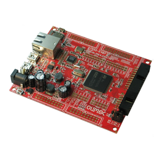
Here you get acquainted with the main parts of the board. Note the names used on the board differ from the names used to describe them. For the actual names check the STM32-E407 board itself. The board comes with a bag with 4 headers for the Arduino/Maple/Pinguino platform which were left unsoldered in case you don't wish to use those environments or you don't plan on using shields. -
Page 10: Layout (Bottom View)
OLIMEX© 2012 STM32-E407 User's Manual 3.2 Layout (bottom view) On the bottom there are three tables printed – general jumper table, boot mode jumper table, power mode jumper table. The default positions of the tables are also shown. Page 10 of 33... -
Page 11: Chapter 4 The Stm32F407Zgt6 Microcontroller
CHAPTER 4 THE STM32F407ZGT6 MICROCONTROLLER 4. Introduction to the chapter In this chapter is located the information about the heart of STM32-E407 – its Cortex-M4F microcontroller. The information is a modified version of the datasheet provided by its manufacturers from ST. - Page 12 OLIMEX© 2012 STM32-E407 User's Manual Cortex-M4 Embedded Trace Macrocell™ 114 I/O ports with interrupt capability Up to 15 communication interfaces 3 × I2C interfaces (SMBus/PMBus) 4 USARTs/2 UARTs (10.5 Mbit/s, ISO 7816 interface, LIN, IrDA, modem control) ...
-
Page 13: Chapter 5 Control Circuity And Hardware Modules
Here you can find information about reset circuit and quartz crystals locations, the power supply circuit is discussed. 5.1 Reset STM32-E407's reset circuit includes R5 (10KΩ), R6 (1 KΩ), C19 (100nF) and a RESET button. 5.2 Clocks There are two quartz crystals available on the board: 12 MHz quartz crystal Q1 is connected to pins 23 and 24 of the CORTEX-M4F processor. -
Page 14: Power Supply Circuit
STM32-E407 User's Manual 5.3 Power supply circuit The power supply circuit of STM32-E407 allows flexible input supply from 6V to 16V direct current. This means a wide range of power supplies, adapters, converters are applicable. The maximum amperage the board can draw is 1A. -
Page 15: Chapter 6 Connectors And Pinout
6.1 JTAG/SWD debug The board can be debugged from the 20-pin JTAG connector either by a JTAG or a SWD compatible debugger. Below is the table of the JTAG. This interface can be used with the Olimex's OpenOCD debuggers. JTAG/SWD interface... -
Page 16: Uext Module
OLIMEX© 2012 STM32-E407 User's Manual We have tested a number of microSD cards on the STM32-E407 boards and all of them worked fine regardless manufacturer or capacity. However, keep in mind that some of the lower quality microSD cards might draw too much current from the slot which might cause power-state problems. -
Page 17: Usb_Otg1
OLIMEX© 2012 STM32-E407 User's Manual PB8/I2C1_SCL PB9/I2C1_SDA PC2/SPI2_MISO PC3/SPI2_MOSI PB10/SPI2_SCK/UART3_TX PG10/UEXT_CS 6.4 USB_OTG1 USB On-The-Go, often abbreviated USB OTG, is a specification that allows USB devices such as digital audio players or mobile phonesto act as a host allowing a USB flash drive, mouse, or keyboard to be attached and also connecting USB peripherals directly for communication purposes among them. -
Page 18: Lan Connector
OLIMEX© 2012 STM32-E407 User's Manual 6.6 LAN connector PIN# SIGNAL NAME NOT CONNECTED NOT CONNECTED NOT CONNECTED Color Usage Right Green Link status Left Yellow Activity status Page 18 of 33... -
Page 19: Arduino/Maple Platform
OLIMEX© 2012 STM32-E407 User's Manual 6.7 Arduino/Maple platform The Arduino/Maple platform connectors (2x6pin and 2x8pin plastic headers) are not mounted but are included in the package. The reasons for not mounting the headers on the pin holes are two: first you might not need them if you do not wish to experiment with Arduino/Maple software;... -
Page 20: 20-Pin Connectors - Pd - Pe - Pf - Pg
OLIMEX© 2012 STM32-E407 User's Manual 6.8 20-pin connectors – PD – PE – PF - PG The 4 20-pin connectors combine different processor ports and provide very nice GPIO option – you can use them with your breadboarding wires, you can mount headers, you can take measures, etc, etc. -
Page 21: Pwr Jack
6.9 PWR Jack The power jack used is the typical 2.5mm one used by Olimex in most of our products. You should provide between 6 and 16 volts @ 1A to the board. Pin #... -
Page 22: Jumper Description
OLIMEX© 2012 STM32-E407 User's Manual there are two vias near them which are actually VCC and can be used if connecting U3BOOT. More information about booting over UART can be found in the processor's datasheet. 6.12 Jumper description Please note some of the jumpers on the board are SMD type. If you feel insecure in your soldering/cutting technique it is better not to try adjusting SMD jumpers. -
Page 23: R-T
OLIMEX© 2012 STM32-E407 User's Manual The default positions are B0_0 and B1_0 (Boot from User Flash Memory). 6.12.3 R-T This is SMD type jumper. If you close/solder this jumper RST and TRST at the JTAG will be connected. The default position is open/unsoldered. -
Page 24: Additional Hardware Components
OLIMEX© 2012 STM32-E407 User's Manual 6.13 Additional hardware components The components below are mounted on STM32-E407 but are not discussed above. They are listed here for completeness: Reset button - used for hardware reset of the board WKUP button – can be used as user button... -
Page 25: Chapter 7 Block Diagram And Memory
OLIMEX© 2012 STM32-E407 User's Manual CHAPTER 7 BLOCK DIAGRAM AND MEMORY 7. Introduction to the chapter On the next page you can find a memory map for this family of processors. It is strongly recommended to refer to the original datasheet released by STMicroelectronics for one of higher quality. -
Page 26: Processor Family Block Diagram
OLIMEX© 2012 STM32-E407 User's Manual 7.1 Processor family block diagram Page 26 of 33... -
Page 27: Physical Memory Map
OLIMEX© 2012 STM32-E407 User's Manual 7.2 Physical memory map Page 27 of 33... -
Page 28: Chapter 8 Schematics
In this chapter are located the schematics describing logically and physically STM32-E407. 8.1 Eagle schematic STM32-E407 schematic is visible for reference here. You can also find them on the web page for STM32-E407 at our site: https://www.olimex.com/dev/STM32-E407.html. They are located in HARDWARE section. - Page 29 OLIMEX© 2012 STM32-E407 User's Manual STM32F407ZET6 PA0/WKUP VDD_1 3.3V P A0/WKUP/USART2_CTS/USART4_TX/ETH_MII_CRS/TIM2_CH1_ETR/TIM5_CH1/TIM8_ETR/ADC123_CH0 PA1/D8/ETH_RMII_REF_CLK VDD_2 PA1/USART2_RTS/USART4_RX/ETH_RMII_RE F_CLK/E TH_MII_RX_CLK/TIM5_CH2/TIM2_CH2/ADC123_IN1 PA2/ETH_RMII_MDIO VDD_3 PA2/USART2_TX/TIM5_CH3/TIM9_CH1/TIM2_CH3/ETH_MDIO/ADC123_IN2 PA3/ETH_RMII_MDINT VDD_4 PA3/USART2_RX/TIM5_CH4/TIM9_CH2/TIM2_CH4/OTG_HS_ULPI_D0/ETH_MII_COL/ADC123_IN3 PA4/D10/SPI1_NSS VDD_5 PA4/SPI1_NSS/SPI3_NSS/USART2_CK/DCMI_HSYNC/OTG_HS_SOF/I2S3_WS/ADC12_IN4/DAC1_OUT PA5/D13/SPI1_SCK VDD_6 PA5/SPI1_SCK/OTG_HS_ULPI_CK/TIM2_CH1_ETR/TIM8_CHIN/ADC12_IN5/DAC2_OUT PA6/D12/SPI1_MISO VDD_7 PA6/SPI1_MISO/TIM8_BKIN/TIM13_CH1/DCMI_PIXCLK/TIM3_CH1/TIM1_BKIN/ADC12_IN6 PA7/D11/ETH_RMII_CRS_DV VDD_8 PA7/SPI1_MOSI/TIM8_CH1N/TIM14_CH1/TIM3_CH2/ETH_MII_RX_DV/TIM1_CH1N/RMII_CRS_DV/ADC12_IN7 PA8/USB_HS_VBUSON VDD_9 PA8/MCO1/USART1_CK/TIM1_CH1/I2C3_SCL/OTG_FS_SOF PA9/OTG_FS_VBUS VDD_10 PA9/USART1_TX/TIM1_CH2/I2C3_SMBA/DCMI_D0/OTG_FS_VBUS...
-
Page 30: Physical Dimensions
OLIMEX© 2012 STM32-E407 User's Manual 8.2 Physical dimensions Note that all dimensions are in millimeters. The three highest elements on the board in order from the tallest to the shortest are: capacitor C50 – 17.2mm (0.677'') over the pcb; LAN connector – 13.6mm (0.535''); capacitators C42 and C48 –... -
Page 31: Chapter 9 Revision History And Support
OLIMEX© 2012 STM32-E407 User's Manual CHAPTER 9 REVISION HISTORY AND SUPPORT 9. Introduction to the chapter In this chapter you will find the current and the previous version of the document you are reading. Also the web-page for your device is listed. Be sure to check it after a purchase for the latest available updates and examples. -
Page 32: Useful Web Links And Purchase Codes
ARM-USB-OCD-H – OpenOCD compatible debugger/programmer with JTAG interface, protection buffers and better power supply circuit SY0612E - power supply adapter 12V/0.5A for STM32-E407 – 220V (European compatibility) The latest price list can be found at http://olimex.com/dev/pricelist.html. How to order? You can order to us directly or by any of our distributors. -
Page 33: Product Support
STM32-E407 User's Manual 9.3 Product support For product support, hardware information and error reports mail to: support@olimex.com. Note that we are primarily a hardware company and our software support is limited. Please consider reading the paragraph below about the warranty of Olimex products.
Need help?
Do you have a question about the STM32-E407 and is the answer not in the manual?
Questions and answers