
Related Manuals for OLIMEX STM32-P405


Summary of Contents for OLIMEX STM32-P405
- Page 1 STM32-P405 development board USER’S MANUAL Revision A, December 2015 Designed by OLIMEX Ltd, 2015 All boards produced by Olimex LTD are ROHS compliant...
-
Page 2: Disclaimer
This document is intended only to assist the reader in the use of the product. OLIMEX Ltd. shall not be liable for any loss or damage arising from the use of any information in this document or any error or omission in such information or any incorrect use of the product. -
Page 3: Table Of Contents
CHAPTER 2: BOARD DESCRIPTION ....................... 7 2.1 Layout (top view) ..........................7 2.2 Prototype area pinout (top view) ......................8 CHAPTER 3 SETTING UP THE STM32-P405 BOARD ................9 3. Introduction to the chapter ........................9 3.1 Electrostatic warning ........................... 9 3.2 Requirements ............................ - Page 4 OLIMEX© 2015 STM32-P405 user's manual 6.4.6 LED_E ............................22 6.4.7 USBP_E ............................. 22 6.4.8 WP_E jumper ..........................22 6.4.9 3.3V_MCU_E jumper ....................... 23 6.5 Additional hardware components ...................... 23 CHAPTER 7 BLOCK DIAGRAM AND MEMORY ................. 24 7. Introduction to the chapter ........................24 7.1 Processor family block diagram ......................
-
Page 5: Chapter 1 Overview
Thank you for choosing this general-purpose development board designed and assembled by Olimex! This document provides a user’s guide for the Olimex STM32-P405 board. As an overview, this chapter gives the scope of this document and lists the board’s features. A comparison between boards similar to STM32-P405 is presented. -
Page 6: Target Market And Purpose Of The Board
UEXT connector; two male extension headers. The board can be powered by a 1.5V AA battery – there is a battery holder provided. Another board, quite similar to STM32-P405, is STM32-P103; the board designs are almost identical – the main difference is that STM32-P103 uses STM32F103RB. -
Page 7: Chapter 2: Board Description
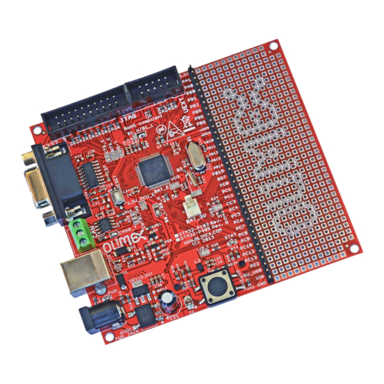
In this chapter you will get acquainted with the main parts of the board. Note the names used on the board differ from the names used to describe them. For the actual names check the STM32-P405 board itself. 2.1 Layout (top view) The picture below shows the top side of the board and highlights the most important parts. -
Page 8: Prototype Area Pinout (Top View)
OLIMEX© 2015 STM32-P405 user's manual 2.2 Prototype area pinout (top view) Below you would find the signals available at the male headers and the prototype area. Each pinhole of the same row of the prototype area has the same signal available. -
Page 9: Chapter 3 Setting Up The Stm32-P405 Board
The placement stability of the board will also increase. 3.2 Requirements In order to set up the STM32-P405 optimally you would need a hardware debugger tool and compatible software tools. More detailed information may be found in the sub-chapters below. -
Page 10: Software Requirements
It is a good idea to study the example that is provided by Olimex for your board. If you are not willing to purchase the software just use the evaluation version initially. Specifically, for STM32-P405 Olimex provides only IAR EW for ARM examples. It is a good idea to download the latest time-limited evaluation version. -
Page 11: Powering The Board
STM32-P405 has a built-in USB DFU bootloader that allows such programming. Programming STM32-P405 via the bootloader is a slow process that requires the re-configuration of SMD jumper. It is not recommend for initial evaluation, research and development (use any ARM JTAG debugger instead). -
Page 12: Using Rs232 Cable And Bootloader Software
– else the bootloader would start every time and the user program (typically stored in the flash memory) would not execute. 3.4.3 Using RS232 cable and bootloader software The access to the serial bootloader is not implemented in STM32-P405. You can't access the bootloader of STM32F405 via the serial interface. 3.5 Prebuilt software Upon powering the board the PWR LEDs should turn on and the STAT LED should blink fast 10 times. -
Page 13: Chapter 4 The Stm32F405 Microcontroller
CHAPTER 4 THE STM32F405 MICROCONTROLLER 4. Introduction to the chapter Some of the details about the main processor in the design of STM32-P405 (STM32F405RG) are mentioned in this chapter. The information is a modified version of the datasheet provided by its manufacturers from ST. - Page 14 OLIMEX© 2015 STM32-P405 user's manual SDIO interface Advanced connectivity USB 2.0 full-speed device/host/OTG controller with on-chip PHY USB 2.0 high-speed/full-speed device/host/OTG controller with dedicated DMA, on-chip full- speed PHY and ULPI 10/100 Ethernet MAC with dedicated DMA: supports IEEE 1588v2 hardware, MII/RMII ...
-
Page 15: Chapter 5 Control Circuity And Hardware Modules
Quartz crystal Q2 is a 32768Hz RTC and it is connected to microcontroller's pins 3 and 4. 5.3 Power supply circuit The power supply circuit of STM32-P405 allows the board to be fully powered from four locations. 1) The recommended location to power the board is the “PWR” barrel jack. You should provide between 6V DC and 12V DC. - Page 16 OLIMEX© 2015 STM32-P405 user's manual from an external battery, an external supercapacitor, or from VDD when no external battery nor an external supercapacitor are present. VBAT operation is activated when VDD is not present. The VBAT pin supplies the RTC, the backup registers and the backup SRAM.
-
Page 17: Chapter 6 Connectors And Pinout
Notes regarding the interfaces are given. 6.1 USB connector The USB type B connector allows you to access the USB functionality of STM32-P405. This connector is can be used to power the board. The connector is sturdy and typically lasts much longer during extensive use compared to the USB mini or USB micro connectors. -
Page 18: Can Connector
The CAN interface behavior can be influenced by the two jumpers CAN0_T and CNTRL/HS. 6.4 UEXT connector STM32-P405 board has UEXT connector and can interface Olimex's UEXT modules. UEXT is a board to board connector which supports three serial communication interfaces – I2C, SPI and RS232. There is also a +3.3V output line and GND. -
Page 19: Pwr_Jack Connector
6.5 PWR_JACK connector The power jack used is the typical one used by Olimex in most of our products – the DC barrel jack has 2.0mm inner pin and 6.3mm hole. More information about the exact component might be found here: https://www.olimex.com/wiki/PWRJACK. -
Page 20: Rs232_2 Connector
Not connected UART2_RTS WAKE-UP (CTS) 6.8 SD/MMC card connector SD/MMC slot is an SD card slot connector, located on the bottom of STM32-P405. It works with the “large” SD and MMC cards. SD/MMC card connector Pin # Connector signal name... -
Page 21: Extension Pins And Prototype Area
OLIMEX© 2015 STM32-P405 user's manual 6.9 Extension pins and prototype area At the right side of the board are is a column of pins. Each of them is connected to a signal – the name of the signal available at a pin is printed next to it. Each of these extension pins carry the same signal as the row of pinholes next to it. -
Page 22: R-T Jumper
OLIMEX© 2015 STM32-P405 user's manual 6.4.4 R-T jumper If you close this jumper RST and TRST at the JTAG will be connected together. The default position of jumper R-T: open.6.4.4 CNTRL/HS The RS pin (pin 8) on the SN65HVD230 provides three different modes of operation: high speed mode, slope control mode, and low-power mode. -
Page 23: V_Mcu_E Jumper
The default state of the jumper is closed. 6.5 Additional hardware components The hardware components below are mounted on STM32-P405 but are not discussed above. These are listed here for completeness: RESET button – used for hardware reset of the board; typically cannot be re-programmed; connected to STM32F405's pin #7 (NRST);... -
Page 24: Chapter 7 Block Diagram And Memory
OLIMEX© 2015 STM32-P405 user's manual CHAPTER 7 BLOCK DIAGRAM AND MEMORY 7. Introduction to the chapter On the next page you can find a memory map for this family of processors. It is strongly recommended to refer to the original datasheet released by STMicroelectronics for one of higher quality. -
Page 25: Physical Memory Map
OLIMEX© 2015 STM32-P405 user's manual 7.2 Physical memory map STM32F405RG has 1024Kbytes of flash memory and (192 + 4)Kbytes of SRAM. Inspecting the map below don't forget that all STM32F405YY microcontrollers have neither Ethernet controller nor camera interface. STM32F405RG also lacks FSMC memory controller. -
Page 26: Chapter 8 Schematics
8. Introduction to the chapter In this chapter are located the schematics describing logically and physically STM32-P405. 8.1 Eagle schematic STM32-P405 schematic is visible for reference here. You can also find them on the web page for STM32- P405 at our site: https://www.olimex.com/Products/ARM/ST/STM32-P405/ They are located in HARDWARE section. - Page 27 47pF(NA) For the STM32F405RET6(LQFP64), please see the corresponding datasheet! WAKE-UP 3.3V VR1(3.3V) LM1117 3.3V LED_E ADJ/GND STM32-P405, board revision D 240/1% DB104(SMD) PWR_JACK 100nF Designed and assembled by Olimex LTD, Bulgaria 390/1% 5VAC https://www.OLIMEX.com 0R(Board_Mounted) 6VDC Page 27 of 31...
-
Page 28: Physical Dimensions
OLIMEX© 2015 STM32-P405 user's manual 8.2 Physical dimensions Note that all dimensions are in millimeters. Page 28 of 31... -
Page 29: Chapter 9 Revision History And Support
OLIMEX© 2015 STM32-P405 user's manual CHAPTER 9 REVISION HISTORY AND SUPPORT 9. Introduction to the chapter In this chapter you will find the current and the previous version of the document you are reading. Also the web-page for your device is listed. Be sure to check it after a purchase for the latest available updates and examples. -
Page 30: Useful Web Links And Purchase Codes
ARM-USB-OCD-H – OpenOCD compatible debugger/programmer with JTAG interface, protection buffers and better power supply circuit How to order? You can order directly from our web-shop or via any of our distributors. List of Olimex distributors may be found here: https://www.olimex.com/Distributors/ Please check https://www.olimex.com/... -
Page 31: Product Support
All goods are checked before they are sent out. In the unlikely event that goods are faulty, they must be returned, to OLIMEX at the address listed on your order invoice. OLIMEX will not accept goods that have clearly been used more than the amount needed to evaluate their functionality.
Need help?
Do you have a question about the STM32-P405 and is the answer not in the manual?
Questions and answers