
Related Manuals for OLIMEX STM32-P407


Summary of Contents for OLIMEX STM32-P407
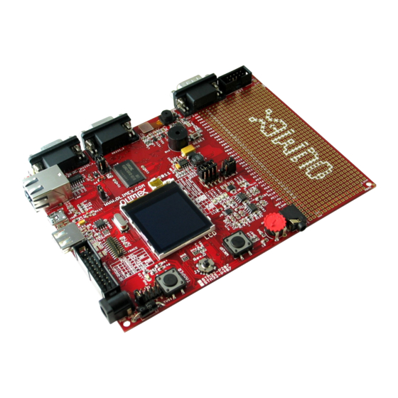
- Page 1 STM32-P407 development board USER’S MANUAL Revision D, May 2014 Designed by OLIMEX Ltd, 2011 All boards produced by Olimex LTD are ROHS compliant...
- Page 2 This document is intended only to assist the reader in the use of the product. OLIMEX Ltd. shall not be liable for any loss or damage arising from the use of any information in this document or any error or omission in such information or any incorrect use of the product.
-
Page 3: Table Of Contents
1. Introduction to the chapter ....................... 5 1.1 Features ............................. 5 1.2 Organization ..........................6 CHAPTER 2 SETTING UP THE STM32-P407 BOARD ........7 2. Introduction to the chapter ....................... 7 2.1 Electrostatic warning ....................... 7 2.2 Requirements ........................... 7 2.3 Powering the board ........................ - Page 4 OLIMEX© 2014 STM32-P407 user's manual 6.16 VGA Color Camera ......................23 6.17 Additional hardware components ..................23 6.18 Notes on interfaces ....................... 23 CHAPTER 7 MEMORY ................... 25 7. Introduction to the chapter ..................... 25 7.1 Memory map .......................... 26 CHAPTER 8 SCHEMATICS ...................
-
Page 5: Chapter 1 Overview
Thank you for choosing the STM32-P407 development board from Olimex! This document provides a User’s Guide for the Olimex STM32-P407 development board. As an overview, this chapter gives the scope of this document and lists the board’s features. The document’s organization is then detailed. -
Page 6: Organization
OLIMEX© 2014 STM32-P407 user's manual Dimensions: 160x116 mm (6.3x4.6") • 1.2 Organization Each section in this document covers a separate topic, organized as follow: – Chapter 1 is an overview of the board usage and features – Chapter 2 provides a guide for quickly setting up the board –... -
Page 7: Chapter 2 Setting Up The Stm32-P407 Board
2.1 Electrostatic warning STM32-P407 is shipped in a protective anti-static package. The board must not be exposed to high electrostatic potentials. A grounding strap or similar protective device should be worn when handling the board. Avoid touching the component pins or any other metallic element. -
Page 8: Powering The Board
On arrival the board has a basic demo installed which features test of the LEDs, the LCD, the joystick, the camera. Note that the demo provided by Olimex LTD is the same as the demo provided for STM32-P207 though not optimized for the F407 processor. -
Page 9: Chapter 3 Stm32-P407 Board Description
3. Introduction to the chapter Here you get acquainted with the main parts of the board. Note the names used on the board differ from the names used to describe them. For the actual names check the STM32-P407 board itself. 3.1 Layout (top view) -
Page 10: Layout (Bottom View)
OLIMEX© 2014 STM32-P407 user's manual 3.2 Layout (bottom view) Page 10 of 32... -
Page 11: Chapter 4 The Stm32F407Zgt6 Microcontroller
CHAPTER 4 THE STM32F407ZGT6 MICROCONTROLLER 4. Introduction to the chapter In this chapter is located the information about the heart of STM32-P407 – its microcontroller. The information is a modified version of the datasheet provided by its manufacturers. 4.1 The microcontroller •Core: ARM 32-bit Cortex™-M4 CPU with FPU, Adaptive real-time accelerator (ART... - Page 12 OLIMEX© 2014 STM32-P407 user's manual •2 × CAN interfaces (2.0B Active) •SDIO interface •Advanced connectivity •USB 2.0 full-speed device/host/OTG controller with on-chip PHY •USB 2.0 high-speed/full-speed device/host/OTG controller with dedicated DMA, on-chip full-speed PHY and ULPI •10/100 Ethernet MAC with dedicated DMA: supports IEEE 1588v2 hardware, MII/RMII •8- to 14-bit parallel camera interface up to 54 Mbytes/s...
-
Page 13: Introduction To The Chapter
Here you can find information about reset circuit and quartz crystal locations. 5.1 Reset STM32-P407 reset circuit includes R65 (10 KΩ), R66(560 Ω), C45(100 nF), STM32F407ZGT6 pin 25 (NRST) and a RESET button. The RESET is also connected to the proto area. -
Page 14: Chapter 6 Hardware
OLIMEX© 2014 STM32-P407 user's manual CHAPTER 6 HARDWARE 6. Introduction to the chapter In this chapter are presented the connectors that can be found on the board all together with their pinout. Proto area is shown. Jumpers functions are described. Notes and info on specific peripherals are presented. -
Page 15: Uext
+5V_TRACE USB_HS_VBUSON TDO/I2S3_CK DCMI_D4 Not connected TDI/I2S3_WS DCMI_D6 DCMI_D7 6.2 UEXT STM32-P407 board has UEXT connector and can interface Olimex's UEXT modules. For more information on UEXT please visit: https://www.olimex.com/Products/Modules/UEXT/ Pin # Signal Name +3.3V DCMI_D0/USART6_TX USART6_RX SOFTWARE SCL SOFTWARE SDA... -
Page 16: Pads On The Proto Area
OLIMEX© 2014 STM32-P407 user's manual 6.3 Pads on the proto area For your convenience the pads are named individually near each of them. Please take extra care about the numbering but consider that there might be offset. PAD # Signal Name... -
Page 17: Usb_Otg
OLIMEX© 2014 STM32-P407 user's manual PAD # Signal Name PAD# Signal Name PE14 PE10 PE13 PE11 PE12 +5V DC VBAT VBAT 6.4 USB_OTG Pin # Signal Name OTG_HS_ID 6.5 USB HOST PIN# SIGNAL NAME +5 V USB_HOST_D- USB_HOST_D+ 6.6 LAN connector... -
Page 18: Pwr Jack
OLIMEX© 2014 STM32-P407 user's manual Color Usage Right Green Link status Left Yellow Activity status 6.7 PWR Jack Pin # Signal Name Power Input 6.8 Headphones connector 6.9 SD/MMC slot Pin # Signal Name DAT2 DAT3/CS CMD/DI CLK/SCLK Page 18 of 32... -
Page 19: Rs232_1
OLIMEX© 2014 STM32-P407 user's manual DAT0/DO DAT1 6.10 RS232_1 RS232_1 is located on USART6/SPI3 line. This interface can be used for accessing the built-in bootloader of STM32F407 microcontroller. You will need DB9 male – DB9 female RS232 cable. You will also need a freely distributed piece of software called “Flash Loader Demo” - it can be downloaded from the official page of the microcontroller under the “Design resources”... -
Page 20: Rs232_2
OLIMEX© 2014 STM32-P407 user's manual 6.11 RS232_2 RS232_2 is located on USART3 (processor pins D13 – D14, A17 – A16) Pin # Signal Name Not connected T1OUT R1IN Not connected Not connected Not connected 6.12 CAN connector Pin# Signal name... -
Page 21: Jumper Description
OLIMEX© 2014 STM32-P407 user's manual 6.14 Jumper description Most of the jumper configurations are printed with white print on the PCB for your convenience. PWR_SEL This jumper control the way the board is powered. There is a table printed on the board with the positions. - Page 22 OLIMEX© 2014 STM32-P407 user's manual 3.3V_MCU_EN When closed enables the power supply on the STM32F207ZET. Default state is closed. TX_BOOT_E If closed separates USART6_TX and PC10. Default state is open. RX_BOOT_E If closed separates USART6_RX and PC11. Default state is open.
-
Page 23: Lcd Display With Backlight
Nokia 6610 color display 128x128 pixels 6.16 VGA Color Camera 640x480 pixels (0.3 mega pixel) Samsung 700 camera + connector 6.17 Additional hardware components The components below are mounted on STM32-P407 but are not discussed above. They are listed here for completeness: Joystick Temperature sensor... - Page 24 OLIMEX© 2014 STM32-P407 user's manual I2C2_SCL - 11 - A0 - the additional memory I2C2_SDA - 10 - A1 - the additional memory I2C3_SCL - 100 - MCO1 - camera interface I2C3_SDA - 99 - SD_D1/DCMI_DB - SD card / camera To my mind, the best idea would be to disable the CAN interface.
-
Page 25: Chapter 7 Memory
OLIMEX© 2014 STM32-P407 user's manual CHAPTER 7 MEMORY 7. Introduction to the chapter On the next page you can find a memory map for this family of processors. It is strongly recommended to refer to the original datasheet released by STMicroelectronics for one of higher quality. -
Page 26: Memory Map
OLIMEX© 2014 STM32-P407 user's manual 7.1 Memory map Page 26 of 32... -
Page 27: Chapter 8 Schematics
In this chapter are located the schematics describing logically and physically STM32-P407. 8.1 Eagle schematic STM32-P407 schematic is visible for reference here. You can also find them on the web page for STM32-P407 at our site: https://www.olimex.com/Products/ARM/ST/STM32-P407/. They are located in HARDWARE section. - Page 28 OLIMEX© 2012 STM32-P407 user's manual 3.3V 3.3V COLOUR LCD MODULE LCD BACKLIGHT CIRCUIT POWER SUPPLY CIRCUIT JTAG 3.3V BL_PWR 3.3V 3.3V 3.3V 3.3V TRACE JTAG 3.3V +5VDC_only!!! TRST/SPI1_MISO CL220uH/SD75 TDO/I2S3_CK TDI/I2S3_WS R100 VDISPLAY R105 TDI/I2S3_WS VDIGITAL TRST/SPI1_MISO R106 1N5819S +5V_TRACE...
-
Page 29: Physical Dimensions
OLIMEX© 2014 STM32-P407 user's manual 8.2 Physical dimensions Note that all dimensions are in inches. Page 29 of 32... -
Page 30: Chapter 9 Revision History
OLIMEX© 2014 STM32-P407 user's manual CHAPTER 9 REVISION HISTORY 9. Introduction to the chapter In this chapter you will find the current and the previous version of the document you are reading. Also the web-page for your device is listed. Be sure to check it after a purchase for the latest available updates and examples. -
Page 31: Web Page Of Your Device
The web page you may visit for more info on your device is https://www.olimex.com/Products/ARM/ST/STM32-P407/. ORDER CODES: STM32-P407 – completely assembled and tested ARM-JTAG-COOCOX – ARM debugger with JTAG and SWD interfaces USB-MINI-CABLE – USB mini to USB-A cable ARM-USB-TINY – for custom programming/debugging ARM-USB-TINY-H –... -
Page 32: Product Support
STM32-P407 user's manual 9.3 Product support For product support, hardware information and error reports mail to: support@olimex.com. Note that we are primarily a hardware company and our software support is limited. Please consider reading the paragraph below about the warranty of Olimex products. - Page 33 Authorized Distribution Brand: Website: Welcome to visit www.ameya360.com Contact Us: Address: 401 Building No.5, JiuGe Business Center, Lane 2301, Yishan Rd Minhang District, Shanghai , China Sales: Direct +86 (21) 6401-6692 Email amall@ameya360.com 800077892 Skype ameyasales1 ameyasales2 Customer Service: Email service@ameya360.com Partnership:...
Need help?
Do you have a question about the STM32-P407 and is the answer not in the manual?
Questions and answers