
Subscribe to Our Youtube Channel
Related Manuals for Landoll Brillion CPPR2-5


Summary of Contents for Landoll Brillion CPPR2-5
- Page 1 ‘ 2-Bar Pick-Up Chisel Plow Models: CPPR2-5, CPPR2-7, CPPS2-5, CPPS2-7 Operator’s and Parts Manual LANDOLL COMPANY, LLC 1900 North Street Marysville, Kansas 66508 (785) 562-5381 800-428-5655 ~ WWW.LANDOLL.COM 9D990-2401...
- Page 2 Instructions for Ordering Parts ** Repair parts must be ordered through an Authorized Dealer ** DEALER INSTRUCTIONS FOR ORDERING PARTS FROM LANDOLL PARTS DISTRIBUTION CENTER Phone #: 800-423-4320 785-562-5381 Fax #: 888-527-3909 Order online: dealer.landoll.com IDENTIFICATION PLATE The identification plate, which lists the model and serial number of the equipment. It is located on the rear right, inside frame of the Chisel Plow.
- Page 3 DANGER DO NOT operate or perform any maintenance tasks on this equipment until you have completed the following: 1. Receive proper training to operate this equipment safely. 2. Read and understand the operator’s manual. 3. Be thoroughly trained on inspection and repair procedures. Failure to comply with this warning may result in serious injury or possibly death.
- Page 5 INDEX Table of Contents Safety Information Introduction ............1-1 Description of Unit .
- Page 6 TABLE OF CONTENTS INDEX Maintenance General Torque Specifications ......... . 4-1 Fasteners .
- Page 7 10 days of retail purchase, using the Landoll injury or death, damage to the machine or its Company, LLC Ag Products on-line registration process.
- Page 8 TABLE OF CONTENTS INDEX SAFETY INFORMATION Safety • Replace decals that become damaged or lost. Also, be sure that any new implement components installed during repair include decals which are NOTE assigned to them by the manufacturer. Investigation has shown that nearly 1/3 of all farm •...
- Page 9 INDEX TABLE OF CONTENTS SAFETY INFORMATION Safety Instructions for Towing Maintenance Safety Vehicles • Do not make adjustments or lubricate the machine while it is in motion or in the raised position. The maximum travel speed is the lesser of •...
- Page 10 TABLE OF CONTENTS INDEX SAFETY INFORMATION Table provided for general use. NOTES: 9D990-2401...
- Page 11 Chapter 2 INDEX TABLE OF CONTENTS Assembly CAUTION Do not work on or under this machine unless securely blocked and supported by a hoist or tractor or by other sufficient means. WARNING Do not attempt to lift heavy parts (such as the frame, rock shaft, and pull hitch) manually.
- Page 12 TABLE OF CONTENTS INDEX ASSEMBLY Main Frame Assembly SMV Sign Assembly of the Main Frame consists of attaching the Attach the SMV Mount about 4 inches left of center on the Mast and Brace Tube. rear Frame Tube with 5/8-11 U-Bolt and Locknuts. See Figure 2-1.
- Page 13 INDEX TABLE OF CONTENTS ASSEMBLY Table provided for general use. NOTES: 9D990-2401...
- Page 14 TABLE OF CONTENTS INDEX ASSEMBLY Shank Installation Place the Frame on blocks at least 30 inches high for assembly of the Shanks. Shank Mounting Dimensions Mark the tubes for Shank locations prior to installing. See Figure 2-3 and 2-4. TOP VIEW FRONT 24"...
- Page 15 INDEX TABLE OF CONTENTS ASSEMBLY TOP VIEW FRONT 24" 24" 24" 12" 12" 24" REAR L.H. and R.H. refer to Left and Right Hand Twisted Shovel Installation. Figure 2-4: Shank Mounting Dimensions (7 Shank) 9D990-2401...
- Page 16 TABLE OF CONTENTS INDEX ASSEMBLY Spring Clamp Shank Assembly Rigid Clamp Shank Assembly Remove the 3/4-10 U-Bolts, Lock Washers and Nuts. Remove the front 3/4-10 x 7-1/2 Bolt, Lock Washer and Place Shank Assembly Clamp under the frame and Nut and loosen the 5/8-11 Nuts so that they are flush with re-insert the U-Bolts over the top of the frame and through the end of the Bolt.
- Page 17 INDEX TABLE OF CONTENTS ASSEMBLY Point Installation NOTE When replacing or reversing point, change ALL points at the same time so that they will have the same operating depth. If some shanks have worn points and some have new points, or points of a different design, the chisel plow will not operate efficiently.
- Page 18 TABLE OF CONTENTS INDEX ASSEMBLY Gauge Wheel Assembly Gauge Wheels for depth, loosen the two U-Bolts but do not remove the nuts. 1. Set the Frame on a level surface with the Shanks 5. Set Gauge Wheels to desired height so that both mounted.
- Page 19 Chapter 3 INDEX TABLE OF CONTENTS Operating Instructions General DANGER • The Chisel Plow loosens the soil to the desired Never allow anyone to ride on the Chisel Plow at depth, allowing water penetration into the soil. During any time. Allowing a person to ride on the the winter, the ground will freeze deeper and machine can inflict serious personal injury or “weather out”...
- Page 20 TABLE OF CONTENTS INDEX OPERATING INSTRUCTIONS Tractor Preparation Field Operation The Chisel Plow may be used on tractors equipped with 1. Lower the Chisel Plow to the ground and pull it a few CAT 2 Free Link or CAT 2, 3N Quick Coupler 3-PT feet at the approximate desired depth.
- Page 21 INDEX TABLE OF CONTENTS OPERATING INSTRUCTIONS Transport 5. Before transporting: • Know the transport heights and widths of the unit 1. Check and follow all federal, state, and local before transporting. Use caution when requirements before transporting the Chisel Plow. transporting near bridges and power lines.
- Page 22 TABLE OF CONTENTS INDEX OPERATING INSTRUCTIONS Table provided for general use. NOTES: 9D990-2401...
- Page 23 Chapter 4 INDEX TABLE OF CONTENTS Maintenance General Torque Specifications (rev. 4/97) This chart provides tightening torques for general purpose applications when special torques are not specified on process or drawing. Assembly torques apply to plated nuts and capscrews assembled without supplemental lubrication (as received condition).
- Page 24 TABLE OF CONTENTS INDEX MAINTENANCE Fasteners Before operating your Brillion machine, check all hardware for tightness. Use the Tightening Torque Table as a guide. See Figure 4-1. After a few hours of use, check entire machine and tighten any loose nuts or bolts. Daily or periodic checks should be made thereafter.
- Page 25 INDEX TABLE OF CONTENTS MAINTENANCE Storage 1. The service life of the Chisel Plow will be extended by proper off-season storage practices. Prior to storing the unit, complete the following procedures: • Completely clean the unit. • Inspect the machine for worn or defective parts. Replace as needed.
- Page 26 TABLE OF CONTENTS INDEX MAINTENANCE Table provided for general use. NOTES: 9D990-2401...
- Page 27 Chapter 5 INDEX TABLE OF CONTENTS Specifications Product Attributes CPPR2 5 CPPS21 5 Approximate Weight 455 lbs. (206 kg) 590 lbs. (268 kg) Working Width 5 ft. 0 in. (1.5 m) 5 ft. 0 in. (1.5 m) Transport Width 6 ft. 6 in. (2.0 m) 6 ft.
- Page 28 TABLE OF CONTENTS INDEX SPECIFICATIONS Product Attributes CPPR2 7 CPPS21 7 Approximate Weight 533 lbs. (242 kg) 722 lbs. (328 kg) Working Width 7 ft. 0 in. (2.1 m) 7 ft. 0 in. (2.1 m) Transport Width 8 ft. 6 in. (2.6 m) 8 ft.
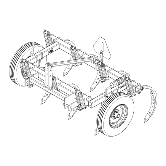
- Page 29 Chapter 6 INDEX TABLE OF CONTENTS Illustrated Parts List Frame Figure 6-1: Frame Frame ITEM PART NUMBER DESCRIPTION 9D976 FRAME ASSEMBLY-CHISEL 9D979 BRACE TUBE 9D978 MAST 6D529 CLEVIS PIN 1.0 X 4.5 5D156 PIN ASSEMBLY 1-1/8X5-3/4 1-557-010327 KLIK PIN 1/4 X 1-1/4 1-654-010059-14 SCREW HX CP 5/8-11X4-1/2 GR5 1-654-010059-13...
- Page 30 TABLE OF CONTENTS INDEX ILLUSTRATED PARTS LIST Rigid Shank Assembly Frame Tube Figure 6-2: Rigid Shank Assembly Rigid Shank Assembly ITEM PART NUMBER DESCRIPTION 6D161 SHANK BUNDLE 26-R 1-654-010061-20 SCREW, HX CP 3/4-10UNC X 7-1/2, G5 1-654-010059-21 SCREW, HEX CAP 5/8-11UNC X 8, GR5 6D298 PLATE 6D234...
- Page 31 INDEX TABLE OF CONTENTS ILLUSTRATED PARTS LIST Shank and Spring Clamp Assembly Frame Tube Part of Spring Clamp Assembly CPP SpringShankAsm Figure 6-3: Shank and Spring Clamp Assembly Shank and Spring Clamp Assembly ITEM PART NUMBER DESCRIPTION 4J681 SPRING CLAMP ASM (SEE PAGE 6-4) 4J293 U-BOLT, 3/4-10 X 6-3/8 X 4-3/4 1-861-010034-17...
- Page 32 TABLE OF CONTENTS INDEX ILLUSTRATED PARTS LIST Spring Shank Assembly 4J681 SpringClampIso Figure 6-4: Spring Shank Assembly 9D990-2401...
- Page 33 INDEX TABLE OF CONTENTS ILLUSTRATED PARTS LIST Spring Shank Assembly ITEM PART NUMBER DESCRIPTION 4J681 SPRING CLAMP ASM 1-512-010005-13 NUT, HEX, SLFLKG GRB 5/8-11 6D409 STRAP 6J459 4K076 COMPRESSION SPRING - OUTER 6D362 COMPRESSION SPRING - INNER 4J675 SHANK CLAMP (7003861) 141776 SCREWHXCP 3/4-10UNCX3-1/2GR5B 8J163...
- Page 34 TABLE OF CONTENTS INDEX ILLUSTRATED PARTS LIST Points Figure 6-5: Points Points ITEM PART NUMBER DESCRIPTION 6D213 CHISEL POINT 6D216 REV. DBL.PT. TW SHOVEL (LEFT) 6D215 REV. DBL.PT. TW SHOVEL (RIGHT) 7K964 SPECIAL PLOW BOLT 4K551 SELF-LOCKING FLANGE NUT (7/16-14) 1/2-13X3PLOW PLOW BOLT GR5 4K552...
- Page 35 INDEX TABLE OF CONTENTS ILLUSTRATED PARTS LIST SMV Assembly Figure 6-6: SMV Assembly SMV Assembly ITEM PART NUMBER DESCRIPTION 2P151 SMV W/BRACKET 164678 MOUNT, SMV 9D989 U-BOLT 5/8-11X5-5/8X4-11/16 1-512-010005-13 NUT,HEX SLFLKG GRB 5/8-11 1-654-010049-05 SCREW HX CP 5/16-18UNCX1 GR5 1-861-010032-09 WASHER, FLAT 5/16 W ZP/CD 104032 NUT,HX SLF-LKG W/MYL 5/16-18...
- Page 36 TABLE OF CONTENTS INDEX ILLUSTRATED PARTS LIST Gauge Wheel Kit (Optional) FRONT Figure 6-7: Gauge Wheel Kit (Optional) Gauge Wheel Kit (Optional) ITEM PART NUMBER DESCRIPTION 9D986 CCP2 GAUGE WHEEL KIT 1-512-010007-11 NUT, HEX 5/8-11 ZP GR2 1-861-010034-15 WASHER 5/8 SLW 9D989 U-BOLT 5/8-11X5-5/8X4-11/16 9D988...
- Page 37 INDEX TABLE OF CONTENTS ILLUSTRATED PARTS LIST Hub and Spindle Assembly Figure 6-8: Hub and Spindle Assembly Hub and Spindle Assembly ITEM PART NUMBER DESCRIPTION 1J398 HUB & SPINDLE ASSEMBLY 1J377 SPINDLE 1J390 WHEEL HUB - 5 BOLT (7001586) (INCLUDES ITEM 3) 1-298-010001-1 ZERK FITTING 1/4 SAE 712099...
- Page 38 TABLE OF CONTENTS INDEX ILLUSTRATED PARTS LIST Wheel Assembly Figure 6-9: Wheel Assembly Wheel Assembly ITEM PART NUMBER DESCRIPTION 6K911 WHEEL 8J789/NO TUBE/4C129 8J789 TIRE - 7.60 X 15 - 6 PLY 4C129 WHEEL - 15 X 5KB - 5 BOLT 8J792 VALVE STEM-TUBELESS 6-10...
- Page 39 BLOCK IMPLEMENT TO PREVENT MOVEMENT WHEN UNHITCHED FROM TRACTOR. 10. KEEP ALL GUARDS AND SHIELDS IN PLACE WHILE MACHINE OR PARTS ARE IN MOTION. 8J310 ITEM 2 - 8J310 MEMBER Landoll Company, LLC Marysville, Kansas www.landoll.com MODEL # SERIAL #...
- Page 40 TABLE OF CONTENTS INDEX ILLUSTRATED PARTS LIST Decal Locations Figure 6-11: Decal Locations 6-12 9D990-2401...
- Page 41 Chapter 12 TABLE OF CONTENTS Glossary For clarity this glossary of industry standard abbreviations and their definitions are provided. For additional information, see instruction on the inside front HHCS ....Hex Head Cap Screw cover or the last page of this manual.
- Page 42 TABLE OF CONTENTS INDEX GLOSSARY RH ....... . Righthand RND ....... . . Round SER .
- Page 43 Chapter 8 TABLE OF CONTENTS Index Numerics 2-573-010198 ......6-11 2J091 ....... . . 1/2-13X3PLOW .
- Page 44 TABLE OF CONTENTS INDEX INDEX 8J163 ........6-5 8J310 .
- Page 45 INDEX TABLE OF CONTENTS INDEX Table provided for general use. NOTES:...
- Page 46 Instructions for Ordering Parts ** Repair parts must be ordered through an Authorized Dealer ** DEALER INSTRUCTIONS FOR ORDERING PARTS FROM LANDOLL PARTS DISTRIBUTION CENTER Phone #: 800-423-4320 785-562-5381 Fax #: 888-527-3909 Order online: dealer.landoll.com IDENTIFICATION PLATE The identification plate, which lists the model and serial number of the equipment. It is located on the rear right hand, inside frame of the Chisel Plow.
- Page 47 Document Control Revision Log: Date Form # Improvement(s): Description and Comments 03/2006 9D990-0306 Initial Release (1273rev3-20-06) 01/2024 9D990-2401 Updated Manual / Revised Template *Revised Form Format “Year/Date”...
- Page 48 Equipment from Landoll Company, LLC is built to exacting standards ensured by ISO 9001 registration at all Landoll manufacturing facilities. 2-Bar Pick-Up Chisel Plow Models: CPPR2-5, CPPR2-7, CPPS2-5, CPPS2-7 Operation’s and Parts Manual Re-Order Part Number 9D990 LANDOLL COMPANY, LLC...
Need help?
Do you have a question about the Brillion CPPR2-5 and is the answer not in the manual?
Questions and answers