
Related Manuals for Pepperl+Fuchs KCT2-6ST-V


Summary of Contents for Pepperl+Fuchs KCT2-6ST-V
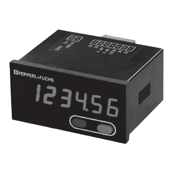
- Page 1 KCT2-6ST-V KC-LED-96-1T-24VDC Pulse counter/Position indicator Bedienungsanleitung Your automation, our passion...
-
Page 2: Safety Instructions And Warnings
KCT2-6ST-V KC-LED-96-1T-24VDC fied personnel. 1. Description The device must compulsorily be The display counter is a multipurpose device. protected with approved external Depending on the programmed basic function, fuses. The value of these fuses can the device operates like be found in the technical information. - Page 3 KCT2-6ST-V KC-LED-96-1T-24VDC 2.2 Mounting in a control panel Take care to separate all extra-low voltages entering or exiting the device from hazardous electrical conductors by means of a double or reinforced Mount the device away from heat insulation (SELV circuits).
-
Page 4: Setting Of The Operating Pa Ra Me Ters
KCT2-6ST-V KC-LED-96-1T-24VDC • The shield connection to the equipotential • Setting of an input signal not matching the bonding should be as short as possible and pulse generator with a contact area as large as possible • Polarity (NPN/PNP) reversed (low-impedance). - Page 5 KCT2-6ST-V KC-LED-96-1T-24VDC g. Hold the left key pressed and press the right Pulse counter/Po si ti on indicator key to switch to the next menu item. (Operating mode pulse counter) h. The last menu title ”EndPro” allows, when se- lecting “Yes”, to exit the programming menu 1.
- Page 6 KCT2-6ST-V KC-LED-96-1T-24VDC 3.1 Polarity of the inputs 3.4 Multiplying factor npn: switching for 0 V It can be set from 00.0001 up to 99.9999. pnp: switching for +U B The decimal point is set to 4 decimal places. „0“ is not accepted! 3.2 Switching on the 30 Hz filter (INP A, INP B)
- Page 7 KCT2-6ST-V KC-LED-96-1T-24VDC 3.8 SET value Tachometer/Frequency meter (Operating mode frequency meter) The device will be set to the set 1. Description point by pressing the red SET/ • 6 digit frequency meter RESET key or activating the • Red LED display, character height 14 mm SET/RESET input.
- Page 8 KCT2-6ST-V KC-LED-96-1T-24VDC 3.2 Switching on the 30 Hz filter 3.7 Max. time to wait until „0“ is displayed This parameter indicates, how long it takes, when measuring is active, until „0“ is displayed. 30 Hz filter off (f 30 Hzfilter on Max.
- Page 9 KCT2-6ST-V KC-LED-96-1T-24VDC 3.3 Input mode • Counting ranges h; min; s; h.min.s • With AC power supply: sensor supply voltage 24 V DC ±15 %/100 mA Start/Stop via Inp B. counting while Inp B (Gate) not active 2. Inputs or open...
-
Page 10: Technical Data
KCT2-6ST-V KC-LED-96-1T-24VDC 3.5 Decimal point 5. Technical data The decimal point defines the Supply voltage resolution of the pro gram med AC power supply: 100 ... 240 VAC/max. 8 VA time unit. Tolerance ±10%, 50/60 Hz ext. fuse protection: T 0.1 A 0.0 1/10 (0,1) - Page 11 KCT2-6ST-V KC-LED-96-1T-24VDC Pulse shape: any, Count frequency: Schmitt-Trigger inputs Frequency measurement Accuracy <0.1 % Sensor supply voltage: Measuring principle: (Voltage output for external sensors) < 38 Hz: period measurement SELV circuit, reinforced/double insulation > 38 Hz: gating time measurement AC power supply 24 V DC ±15 %/100 mA...
-
Page 12: Terminal Assignment
100...240 VAC ±10% 10 ... 30 V DC 7. Delivery includes: Digital display 2 pin screw terminal RM 5.08 7 pin screw terminal RM 3.81 Panel mounting clip Seal Multilingual operating instructions 8. Ordering code: 100...240 VAC ±10%: KCT2-6ST-V 10-30 VDC: KC-LED-96-1T-24VDC ENG / 11... - Page 14 Pepperl+Fuchs Quality Download our latest policy here: www.pepperl-fuchs.com/quality Weltweit Pepperl+Fuchs SE Lilienthalstraße 200 68307 Mannheim Deutschland Telefon: +49 621 776-0 E-Mail: info@de.pepperl-fuchs.com https://www.pepperl-fuchs.com Änderungen vorbehalten · © Pepperl+Fuchs Printed in Germany DOCT-1814B R60017.9396 - Index 5 · 10/2023...
Need help?
Do you have a question about the KCT2-6ST-V and is the answer not in the manual?
Questions and answers