Table of Contents

Summary of Contents for TMQ C-Drive 5
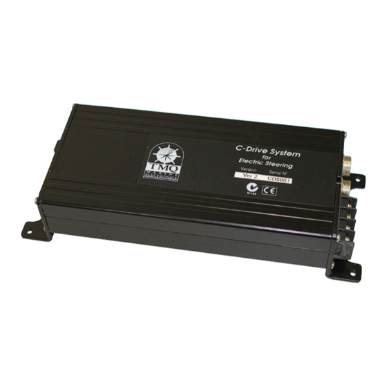
- Page 1 C-Drive 5 Motor Control Unit for Electric Steering & Autopilots Installation and Service Manual Unit 18, 17 Rivergate Place Murarrie QLD 4172 T: +61 07 3640 5600 E: tmq@tmq.com.au www.tmq.com.au IMPORTANT: PLEASE RETAIN ON BOARD...
- Page 2 (This page intentionally left blank)
-
Page 3: Table Of Contents
Electric Helm with Hydraulic Steering Definition of Terms Installation C-Drive Unit Autopilot Options DIP Switch Setting DIP Switch Location Rudder Feedback Precautions Main Display Unit Compass - TMQ Electronic Compass (Elecom) Remote Units Remote Configuration Options Special Remote Modes (Refer Setup Procedure) System Configuration Normal Configuration Solenoid Configuration... -
Page 4: Introduction
• Drive units, for example 2. Computer operating software, - Hydraulic system with solenoid AP1000 or, valves. 3. TMQ Active remote, and - Reversing hydraulic pump system. 4. F luxgate compass - Mechanical motor drive system. (d) With the addition of control display... -
Page 5: Dual Station Electric Steering
Block Diagram – Electric Steering System Dual Station Electric steering Electric Helm with Hydraulic Steering Version 2.0 Rev 1 October 2021 3 of 36... -
Page 6: Definition Of Terms
Rudder Angle Indicator (RAI) Mechanical Drive, a reversing motor drive unit with reduction gears to drive This is an analogue display which the steering system. shows the current rudder position. • Linear actuator, either hydraulic or mechanical 4 of 36 TMQ C-Drive 5 Manual... -
Page 7: Installation
Installation C-Drive Unit * Note: Power cable must be • Select a dry position connected via a 15 amp circuit • Provide room for access for breaker or via a 15 amp fused technical adjustments circuit with isolating switch to 12/24 • Provide access for cables and VDC supply connections both ends •... -
Page 8: Autopilot Options
IF A RUDDER FEEDBACK IS NOT on when a GPS and COG FITTED, OR IF THE FEEDBACK is used as the heading IS FAULTY OR INCORRECTLY reference input. ADJUSTED. THE RUDDER FEEDBACK UNIT IS FACTORY ALIGNED. THE ARM 6 of 36 TMQ C-Drive 5 Manual... -
Page 9: Rudder Feedback Precautions
SHOULD NOT BE REMOVED • Remove the top of the feedback OR LOOSENED. IF ARM IS (RFUH only) LOOSENED OR REMOVED, • Connect 3 core cable to the RFU VOLTAGE ALIGNMENT SHOULD terminal strip (RFUH only) BE CHECKED BEFORE USING THE •... - Page 10 Standard Rudder Feedback 8 of 36 TMQ C-Drive 5 Manual...
- Page 11 Heavy Duty Rudder Feedback Version 2.0 Rev 1 October 2021 9 of 36...
- Page 12 Note 1: if using RFUH connect as shown below. Set the c-drive internal Pin1 Rudder signal dip switches to RFUH. (Green) Pin2 +5v (Red) Pin3 Not Used Pin4 0 v (Blue) Pin5 Link to Pin 1 10 of 36 TMQ C-Drive 5 Manual...
-
Page 13: Main Display Unit
• Rotate compass in the bracket until current carrying cables. cable is pointing astern Compass - TMQ • Route cable to C-Drive position avoiding proximity to radio, aerial The normal compass supplied for... -
Page 14: Electronic Compass (Elecom)
• Connect compass cable to the NMEA socket of the C-Drive E-Compass Mounting Vessel Bow Connections – Wire Colour Code Wire colour Signal from Pin Elecom Red +10 V 6 Black (shield) V- 4 Green Yellow 5 Blue *Close Link J4 on PCB. 12 of 36 TMQ C-Drive 5 Manual... - Page 15 Display - Connection for Head units and GPS Data Pin 1 NMEA One Input + Pin 2 NMEA One Input – Pin 3 Transmit NMEA Data + TMQ Display Data Pin 4 0 VDC Power out Negative Pin 5 NMEA Two Input + TMQ Display Data Pin 6 +10 Vdc Power out Display Power NMEA - Connection NMEA Data In/Out, Electronic Compass.
- Page 16 Note: The operation of remotes is dependent on the internal special remote mode settings of the C-Drive amplifier. There is a range of diverse settings which allow a boat to be customised for a given application. Consult your dealer or TMQ Electronics for further information. The internal terminal block in the C-Drive unit has the following connections: Pin 1 REMP Remote Power – 5V...
- Page 17 NMEA Heading Data I/O & External Alarm Connection The internal terminal block in the C-Drive unit has the following connections: Pin 1 REMP Remote Power – 5V Pin 2 WIP3 Wiper Input for Remote 3 Pin 3 SEL3 Select Input for Remote 3 Pin 4 Neg Negative Pin 5 ALM-...
- Page 18 (linear hydraulic actuator) or a mechanical drive with electric clutch, the valve or clutch is connected to B1 and B2 Note: The motor wires may require reversing to provide the correct rudder direction movement 16 of 36 TMQ C-Drive 5 Manual...
- Page 19 Reversing Hydraulic Pump Solenoid Valve (or Relay) Connection Version 2.0 Rev 1 October 2021 17 of 36...
-
Page 20: Remote Units
Note: When connecting the C-Drive TMQ Active Remote to be connected for solenoid operation, two internal to Remote socket (Remote Mode 2 links J1 and J2 on the PCB must must be set). be cut if jog switches are fitted and The C-Drive unit can be configured connected directly to the C-Drive to operate in a number of different Output. - Page 21 Note: Refer System Examples There are two main setting options for the C-Drive which cover a majority section Remote Mode 1 and Remote of the common installations: Mode 4 for diagrams of these configurations. • Mode 1 - used when the C-Drive is not the primary mode of Additionally, there are special remote steering the vessel modes for specific installation...
- Page 22 Remote 3 input: 1 Standard Remote, use of different remotes, such as inside terminal. 3 wheels, or 3 remotes, or TMQ active remotes. Remote Mode 3 – 2 Remotes and Wheel used in power steer mode: Remote Mode 1 – Additional...
-
Page 23: System Configuration
This is the width of the pulse (the compass. Its default value is already ‘ON’ time) per period – determined by calibrated for working with TMQ the period of control. compasses, and usually will not be necessary to be changed. -
Page 24: Normal Configuration
0 to 20 0 to 20 The above settings can be altered depending on the specific requirement of the installation. This can be carried out by a TMQ dealer or by using a computer and the computer lead (lead not supplied – see details on page 25) 22 of 36... -
Page 25: Solenoid Configuration
8. Press [Shift] then key in the text “@cal” Then press [Ctrl] and [Enter] Note: The text is not visible as it is typed. The ‘TMQ Steering Unit’ configuration option menu will now 4. S tart a new connection and name it be displayed. for example “Electric Steering”. -
Page 26: Setup Options Menus
5: Period of ctrl for NO RFU 8: View GPS Steering Data 6: Min speed for NO RFU 9: Current Rate Data 7: Heading deadband A: Centre Rudder in Auto 8: Max correction error (P) R: RFU Centre Data Q. Quit Q-Quit 24 of 36 TMQ C-Drive 5 Manual... -
Page 27: Remote Calibration
Remote Calibration Rudder must be driven. Following it is described how each of these The remotes may require calibration values contributes to the control of to provide full rudder travel from each the vessel. remote. Proceed as follows: • Select main menu (refer Set up page •... -
Page 28: Testing Procedure
Check rudder direction follows Wheel or Lever Check Wheel or Lever provides sufficient rudder movement Adjust Rudder Limits using a display or computer if required IMPORTANT: Always initially test system at low speeds first in open water during calm conditions. 26 of 36 TMQ C-Drive 5 Manual... -
Page 29: Trouble Shooting
Trouble Shooting Unit does not move rudder Solenoid valves do not operate • Check voltage is present at the • Check the motor connections on Electric Steering Unit power plug. the C-Drive amplifier • C onfirm that the supply voltage is in • Check connections on solenoid the range of 12-24 volts dc. -
Page 30: Optional Extras
The C-Drive system can be adapted maintain full control of the autopilot to suit many applications. and steering while moving around the For further information see the TMQ vessel. website www.tmq.com.au AP56 Display Rudder Angle... - Page 31 Continuous pumps Constant running pumps available in varying flow rates for 12 / 24 volt DC systems and 240 / 415 volt AC systems. Accurate flow adjustment to set lock-to-lock time available on some units Linear drive (hydraulic) Single rod linear drives can be fitted to a wide variety of vessels. May be attached directly to the tiller or rudder quadrant Mechanical drive (rotary) Mechanical drive units in 12 or 24 volt DC to suit vessels with existing mechanical steering.
-
Page 32: Circuit Diagram
Circuit Diagram 30 of 36 TMQ C-Drive 5 Manual... -
Page 33: Pcb Layout
PCB Layout Version 2.0 Rev 1 October 2021 31 of 36... -
Page 34: Declaration Of Conformity
TMQ Electronics, whose address EN60945/1997 is unit 18, 17 Rivergate Place, CEI IEC945/1996 Murarrie QLD 4172. For TMQ International Pty. Ltd. 2. Proof of purchase is supplied Murarrie Queensland Australia. and original Serial Numbers on equipment have not been changed. 3. Information is provided regarding the nature of the failure or problem occurring. - Page 35 The owner is also responsible for providing reasonable maintenance and weather protection of the equipment. TMQ Electronics shall not be liable for damage or loss incurred resulting from the use and operation of this product. TMQ Electronics reserves the right to...
- Page 36 Unit 18, 17 Rivergate Place Murarrie QLD 4172 T: +61 07 3640 5600 E: tmq@tmq.com.au www.tmq.com.au...
Need help?
Do you have a question about the C-Drive 5 and is the answer not in the manual?
Questions and answers