Advertisement
Quick Links
20cc
Gas Engine
Glow 120 4T
RADIO CONTROL MODEL / RC FLUGMODELL
BUILDING INSTRUCTIONS / MONTAGEANLEITUNG
SPECIFICATIONS
Wingspan
Length
Flying weight
Gas Engine
Radio
Technische Daten
Spannweite
Länge
Fluggewicht
Verbrennerantrieb
Fernsteuerung
WARNING! This radio controlled model is NOT a toy. If modified or flown carelessly it could go out of controll and
cause serious human injury or property damage. Before flying your airplane, ensure the air field is spacious enough.
Always fly it outdoors in safe areas and seek professional advice if you are unexperienced.
ACHTUNG! Dieses ferngesteuerte Modell ist KEIN Spielzeug! Es ist für fortgeschrittene Modellflugpiloten bestimmt,
die ausreichende Erfahrung im Umgang mit derartigen Modellen besitzen Bei unsachgemäßer Verwendung kann
hoher Personen- und/oder Sachschaden entstehen. Fragen Sie in einem Modellbauverein in Ihrer Nähe um
professionelle Unterstützung, wenn Sie Hilfe im Bau und Betrieb benötigen. Der Zusammenbau dieses Modells ist
durch die vielen Abbildungen selbsterklärend und ist für fortgeschrittene, erfahrene Modellbauer bestimmt.
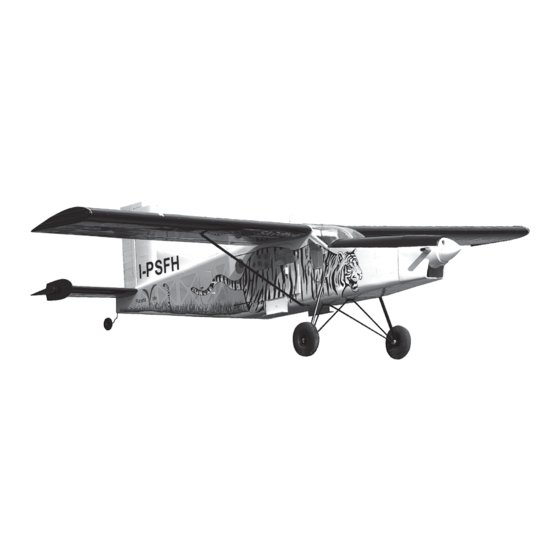
Pilatus
Porter
Semi scale model
85.4 in.
59.8 in.
14.4 lbs
20cc
6 Channel / 8 servos
2.170mm
1.520mm
4.500g
20cc
7 Kanal / 8 Servos
PC-6
Advertisement

Related Manuals for VQ Pilatus Porter PC-6


Summary of Contents for VQ Pilatus Porter PC-6
- Page 1 20cc PC-6 Pilatus Gas Engine Porter Glow 120 4T Semi scale model RADIO CONTROL MODEL / RC FLUGMODELL BUILDING INSTRUCTIONS / MONTAGEANLEITUNG SPECIFICATIONS Wingspan 85.4 in. Length 59.8 in. Flying weight 14.4 lbs Gas Engine 20cc Radio 6 Channel / 8 servos Technische Daten Spannweite 2.170mm...
- Page 2 REQUIRED FOR OPERATION (Purchase separately) BENOTIGTE KOMPONENTEN FUR DEN ABFLUG (Nicht enthalten) Extension for aileron servo, Flap servo. Glow 120 4T Engine Gas Engine: 20cc Minimum 7 channel radio for airplane 900 - 1.000Watts with 5 standard servos and 3 mini servos Brushless Motor Flapx2 standard servo - Aileronx2 standard servo Rudderx1 standard servo - Elevatorx2 mini servo...
- Page 3 1- Landing gear / Fahrwerk 5.5mm Collar Stellring 3x12mm screw Stopper (metal) 5.5mm Collar ....8 Stopper (metal) ...2 ...4 Nylon strap Kunststoffstreifen 3mm set screw 5mm landing Collar ....4 ....4 gear BOTTOM - VIEW / Unteransicht Aluminum tube 5mm landing gear 5mm Main landing gear (front) Caution: All holes on the bottom of the...
- Page 4 4- Tail gear / Heckspornrad BOTTOM - VIEW / Unteransicht Tail gear control arm (B) Nylon rudder torque rod bearing..1 ..1 Rudder torque rod. Tail gear control arm (B) Tail gear control arm (B) Note: Slide the tail gear push rod in to the hole of the tail gear control arm B first.
- Page 5 6- Vertical Stabilizer Cut 7/8” (22mm) long slots along the hinge line in the Seitenleiwerk trailing edge of the vertical stabilizer for the rudder torque rod bearings. Position of the slot on the side of the vertical stabilizer, 2”(50mm) from the bottom (6A) Test-fit the rudder torque rods into the slot.
- Page 6 7- Horizontal Stabilizer Hohenleitwerk 30x4mm nylon bolt ....3 Horizontal stabilizer Using a pencil, mark the rudder where the rudder torque rod meet the rudder. Cut 2.3” (60mm) long slots along the hinge line in the leading edge of the rudder. Drill a 3/32”(2.5mm) diameter hole in tail wheel gear mounting slot, marking sure that you drill the hole perpendicular to the leading edge of the rudder (7C).
-
Page 7: Bottom View
8- Horizontal Stabilizer Control horn Hohenleitwerk ......2 2x30mm screw ....4 9- Servo & Linkages BOTTOM - VIEW Unteransicht Threadlocker... -
Page 8: Glow Engine
10- Engine - Cowl / Motor - Motorhaube ! Align the center mark on the engine with the mark on the fire-wall. Remove the engine mount and drill a 13/64”(5mm) hole Using a pencil or felt tipped pen, mark the fire wall through the fire-wall at each of the four marks marked (10B). -
Page 9: Brushless Motor
FRONT-VIEW 12- Brushless Motor Plywood motor mounting plate Vorderansicht Sperrholztrager Platten - Using a plywood motor mounting plate as a template, mark the fire wall where the four holes are to be drilled (12A). - Remove the plywood motor mounting plate and drill a 13/64”(5mm) hole through the fire-wall at each of the four marks marked (12B). - Page 10 13- Fuel tank / Tankeinbau Full the magnetic battery hatch out of the fuselage. Put the Li-Po battery in place. Magnetic battery hatch. Put the fuel tank in place. 14- Servo Aileron control horn Threadlocker Aileron servo extension cord Control horn ......2 2x30mm screw .....4...
- Page 11 15- Installing the wing / Tragflacheneinbau Aluminum tube Wooden dowel Wooden dowel 16- Installing the wing / Tragflacheneinbau 3x15mm screw / Schraube ......2 ......2 The blind-nut on the bottom of the wing installed at factory The holes on the bottom of the wings and side of 3x15mm the fuselage are pre-drilled...
- Page 12 17- Decor / Aufkleber Sticker IMPORTANT: Please do not clean your model with pure alcohol, only use liquid soap with water or use glass cleaner to clean on surface of your model to keep the colour not fade. Sticker All details are subject to change Technische Anderungen und Irrtumer without notice ! vorbehalten !
Need help?
Do you have a question about the Pilatus Porter PC-6 and is the answer not in the manual?
Questions and answers