Table of Contents
Advertisement
Quick Links
60 Class
2-cycle engine
90 Class
4-cycle engine
SPECIFICATIONS
Wingspan
Length
Flying weight
Electric Motor
800 Watt (BOOST 60)
Glow Engine
Radio
5 Channel / 6 Servos
Technische Daten
Spannweite
Länge
Fluggewicht
Elektroantrieb
800 Watt (BOOST 60)
Verbrennerantrieb
Fernsteuerung
WARNING! This radio controlled model is NOT a toy. If modified or flown carelessly it could go out of controll and
cause serious human injury or property damage. Before flying your airplane, ensure the air field is spacious enough.
Always fly it outdoors in safe areas and seek professional advice if you are unexperienced.
ACHTUNG! Dieses ferngesteuerte Modell ist KEIN Spielzeug! Es ist für fortgeschrittene Modellflugpiloten bestimmt,
die ausreichende Erfahrung im Umgang mit derartigen Modellen besitzen Bei unsachgemäßer Verwendung kann
hoher Personen- und/oder Sachschaden entstehen. Fragen Sie in einem Modellbauverein in Ihrer Nähe um
professionelle Unterstützung, wenn Sie Hilfe im Bau und Betrieb benötigen. Der Zusammenbau dieses Modells ist
durch die vielen Abbildungen selbsterklärend und ist für fortgeschrittene, erfahrene Modellbauer bestimmt.
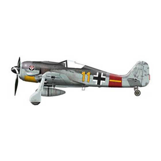
Semi scale model
BUILDING INSTRUCTIONS / MONTAGEANLEITUNG
1610mm
1220mm
2900g
7,5cc 2T / 8,5cc 4-T
1610mm
1220mm
2900g
7,5cc 2T / 8,5cc 4T
5 Kanal / 6 Servos
FW-190A
Focke-Wulf
11
13
170393
Advertisement
Table of Contents

Related Manuals for VQ FW-190A FOCKE-WULF


Summary of Contents for VQ FW-190A FOCKE-WULF
- Page 1 60 Class FW-190A 2-cycle engine Focke-Wulf 90 Class 4-cycle engine Semi scale model BUILDING INSTRUCTIONS / MONTAGEANLEITUNG 170393 SPECIFICATIONS Wingspan 1610mm Length 1220mm Flying weight 2900g Electric Motor 800 Watt (BOOST 60) Glow Engine 7,5cc 2T / 8,5cc 4-T Radio 5 Channel / 6 Servos Technische Daten Spannweite...
- Page 2 REQUIRED FOR OPERATION (Purchase separately) 12x6 for .60 - 4 cycle engine Extension for aileron 13x7 for .90 - 4 cycle engine servo, retract servo. 14X8 for Quantum 4120/07 Phoenix-60 Brushless Motor Control or equivalent. Retract landing gear VQAR010 Retract servo Brushless Motor .90 - 4 cycle .60 - 2 cycle...
-
Page 3: Joining The Wing
TOP-VIEW 1- Joining the wing Center line 1- Using a pencil, mark the center of the brace. 2- Trial fit the wing joiner into one of the wing panels. It should insert smoothly up to the center line marked above. 3- Slide the other wing half onto the dihedral brace until the wing panel meet. - Page 4 4- Flap servo TOP-VIEW FLAP SERVO INSTALLATION Flap servo Note: The head of servo should be positioned toward the front of the wing. Flap servo WING WING SECTION SECTION BOTTOM 5- Flap - Linkage Retract servo Flap rod Flap rod CLOSE POSITION CLOSE POSITION Flap rod...
-
Page 5: Fixed Gear
With the retract and retract servo in the retracted position, mark the position 7- Retract landing gear where each of the pushrod will attach to the servo arm, a small piece of masking tape works well for this. Cut off the excess length each rod. Link the servo and retract gear arm with push rod. -
Page 6: Aileron Servo
10- Fixed gear ABS wheel well cover (for fixed gear) BOTTOM VIEW 11- Aileron servo Aileron servo hatch (ply 3mm) Included with the Aileron servo 5/64(2x10mm) radio set extension screw cord Plastic control horn 5/64(2x20mm) ....2 screw 2x20mm screw ....4 5/64”... -
Page 7: Vertical / Horizontal Stabilizer
Trial fit each part before gluing . Be certain that there 13- Vertical / Horizontal stabilizer are no gaps. If the parts will join, but with a gaps, sand or trim the parts a little at a time until the parts meet exactly with no gaps. - Page 8 BOTTOM VIEW 15- Servo Rudder servo Throttle servo NOTE: Place of throttle servo may be change Switch hole depend of engine (Four-stoke or two-stroke engine) Elevatorservo 16- Linkages Connector BOTTOM VIEW ...2 Connector ....3 Elevator push rod Tail wheel push rod Elevator servo 2mm screw Throttle servo...
-
Page 9: Engine Mount
17- Engine mount 4x25mm screw ! Align the mark on both mounts ....4 with the mark on the fuselage Blind-nut ! Engine thrust on balk head ......4 is already adjust at factory FRONT-VIEW 13/64” B’ FRONT-VIEW B=B’ 18- Engine 124 ~ 127mm (IN CASE OF 2T ENGINE) TOP-VIEW With hang silencer (Pitts-style) -
Page 10: Electric Motor
FUEL TANK INSTALLATION 19- Fuel tank To muffler Filler tube Rubber stopper After confirming the direction, Insert this assembly, clunk end first, into To engine Fuel tube Stopper the fuel tank and tighten and screw the fuel tank cap on firmly. Using a aluminum motor mounting plate as 20- Electric motor a template, mark the plywood motor mounting... - Page 11 Attach the board or transparent plastic on the side of 22- Cowling the fuselage with the adhesive tape as show. Using a pencil or felt tipped pen trace around the engine 2.5x10mm screw head where it meet the cowl. Cut the opening the board or transparent plastic for the engine head as marked ..4 above.
- Page 12 23- Hatch Magnetic hatch. Securely install the battery, ensuring it will not come rattle during flights. 24- Wing cover 6x50mm nylon bolt 6X50mm bolt ...2 Plastic wing cover 12mm Using the plastic wing cover as a 15/32” template, trace around the outside edge of the plastic wing cover and then remove it.
- Page 13 26- Canopy Secure the canopy in place with adhesive tape . When satisfied with the fit, drill six holes on the each side of canopy as show. Remove the canopy from the fuselage and apply litter CA glue into the screwed hole to make reinforcement.
- Page 14 29- Tail gear cover BOTTOM-VIEW Plastic tail gear cover 2x10mm..6 3/64” 30- Decor 170393 Note: Cut out the stickers and apply them in the proper area. Do not peel the backing paper off all at once. Peel off one corner of the backing and cut off with scissors. Arrange sticker on model and when satisfied adhere the corner without backing.
-
Page 15: Control Surface
32- Control surface 15/64”(6mm) 15/64”(6mm) 13/32” AILERON STROKE (10mm) 13/32” ELEVATOR STROKE (10mm) 51/64”- 1-3/16” 1-23/64” (20 - 30mm) (35mm) FLAP STROKE 1-23/64” RUDDER STROKE (35mm) Adjust the travel of the control surfaces to achieve the values stated in the diagrams. These value will be suitable for average flight requirements.
Need help?
Do you have a question about the FW-190A FOCKE-WULF and is the answer not in the manual?
Questions and answers