Table of Contents
Advertisement
Quick Links
VQ No: VQA095
Instruction manual / Montageanleitung
SPECIFICATIONS
Wingspan:.........................1560mm (61.4in)
Length:................................1170mm (46 in)
Electric Motor:.....................See next pager
Glow Engine:.................... .46 2-T / .70 4-T
RTF Weight: 3.2Kg / 7.05lbs (Will vary with
Equipment Used).
Radio:......................6 Channel / 6-7 Servos
Function: Ailerons-Elevator-Rudder-Throttle
Flaps-Optional Retractable Landing Gear.
WARNING! This radio controlled model is NOT a toy. If modified or flown carelessly it could go out of controll and
cause serious human injury or property damage. Before flying your airplane, ensure the air field is spacious enough.
Always fly it outdoors in safe areas and seek professional advice if you are unexperienced.
ACHTUNG! Dieses ferngesteuerte Modell ist KEIN Spielzeug! Es ist für fortgeschrittene Modellflugpiloten bestimmt,
die ausreichende Erfahrung im Umgang mit derartigen Modellen besitzen. Bei unsachgemässer Verwendung kann
hoher Personen- und/oder Sachschaden entstehen. Fragen Sie in einem Modellbauverein in Ihrer Nähe um
professionelle Unterstätzung, wenn Sie Hilfe im Bau und Betrieb benötigen. Der Zusammenbau dieses Modells ist
durch die vielen Abbildungen selbsterklärend und ist für fortgeschrittene, erfahrene Modellbauer bestimmt.
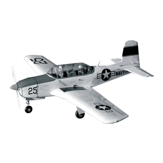
Radio control model / Flugmodel
BEECHCRAFT
MILITARY TRAINER
ALL BALSA, PLYWOOD CONSTRUCTION AND ALMOST READY TO FLY
TECHNISCHE DATEN
Spannweite:...................................1560mm
Lange:............................................1170mm
Elektroantrieb.............(siehe nächste Seite)
Verbrennerantrieb:...............7.45cc - 11.5cc
Fluggewicht:.......................................3.2Kg
Fernsteuerung.............6 Kanal / 6-7 Servos
Advertisement
Table of Contents

Related Manuals for VQ T-34 Mentor


Summary of Contents for VQ T-34 Mentor
- Page 1 Radio control model / Flugmodel BEECHCRAFT MILITARY TRAINER VQ No: VQA095 ALL BALSA, PLYWOOD CONSTRUCTION AND ALMOST READY TO FLY Instruction manual / Montageanleitung TECHNISCHE DATEN SPECIFICATIONS Wingspan:......1560mm (61.4in) Spannweite:........1560mm Length:........1170mm (46 in) Lange:..........1170mm Electric Motor:.....See next pager Elektroantrieb.....(siehe nächste Seite) Glow Engine:....
- Page 2 REQUIRED FOR OPERATION (Purchase separately) More info: www.pichler-modellbau.de 10.5x6 for .40 - 2 cycle engine 11x6 for .46 - 2 cycle engine 12x6 for .60 - 4 cycle engine Extension for aileron 12x7 for .70 - 4 cycle engine servo, retract servo 13x7 - 13x8 for electric motor and Rx battery pack.
- Page 3 1-Aileron and Flap servo Included with the radio set. WING - BOTTOM VIEW Adhesive tape -Switch on the radio (trims centered) then mount the ailerons servo horn 1-Cut away the covering of the wing bottom in neutral position. where the aileron servo goes. -The servo horn should be 2-Connect the aileron servo cord to the aileron perpendicular to the servo...
-
Page 4: Fixed Gear Installation
4-Electric retract Electric retract must be purchase separately EXTENDED POSITION RETRACTED POSITION ELECTRIC RETRACT LANDING GEAR GEAR RECEIVER Do the same way with second wing half. 5-Fixed gear Main landing gear 3x12mm screw 3x20mm ..8 3x20mm screw ..16 Nylon gear strap Square plastic x 2 Nylon gear strap... -
Page 5: Horizontal Stabilizer
7-Horizontal Stabilizer Securely glue together. If coming off during flight, you lose control of your air plane. Cut away only the covering both the right and left side B’ Cut away only the covering both the top and bottom side A = A’... - Page 6 9-Elevator Securely glue together. If coming off during flight, you lose control of your air plane. 1-Trial fit the horn. Actuate rudder linkage manually it should not be hard spot. Adjust if necessary. 2-Insert the plate through the foot of the horn. Bond with thin CA glue.
- Page 7 11-Engine mount / Engine ! Align the mark on both mounts with the mark on the fuselage 1/8x5-1/64” 5/32x1” 4x25mm screw 3x20mm screw B’ ...4 ...4 Blind-nut 1/8”(3mm) nut FRONT-VIEW ....4 ....4 B=B’ Reposition the engine mounts on to the fire-wall. Using a pencil or felt tipped pen, Remove the engine mount and drill a Attach the four blind-nut to the fire-wall as show.
-
Page 8: Electric Motor
13-Electric Motor Using a aluminum motor mounting plate as a template, mark the plywood motor mounting plate where the four holes are to be drilled . Remove the aluminum motor mounting plate and drill a 1/8”(3mm) hole through the plywood at each of the four marks marked . - Page 9 16-Linkages FUSELAGE - TOP VIEW Elevator servo Throttle pushrod FUEL TANK OR LI-PO BATTERY AREA Nose gear pushrod Rudder servo Elevator push rod Elevator pushrod 3mm set Screw Elevator pushrod Elevator push rod Rudder push rod 2 mm Connector ....1 ....3 17-Installation the Wing FUSELAGE - TOP...
- Page 10 18-Installation the Wing WING 19-Installation the wing 4x25mm screw 4X25mm screw ..2 ..2 WING...
- Page 11 20-Canopy 4x20mm nylon screw 21-Decor Cut away only the covering 22-Decor Note: Cut out the stickers and apply them in the proper area. Do not peel the backing paper off all at once. Peel off one corner of the backing and cut off with scissors. Sticker: See the top of the box Arrange sticker on model and when satisfied adhere the corner without backing.
-
Page 12: Control Surface
23-Decor Gear door (3mm plywood) Lighting Lighting extension cord (not included) Please do not glue here. To any channel on your receiver 3v - 6v led (pre-installed) Note: Glue the Right and Left gear door on to the cowl only. Please do not glue them on to the fuselage if you want to remove the cowl out of the fuselage.
Need help?
Do you have a question about the T-34 Mentor and is the answer not in the manual?
Questions and answers