Advertisement
Quick Links
1
.
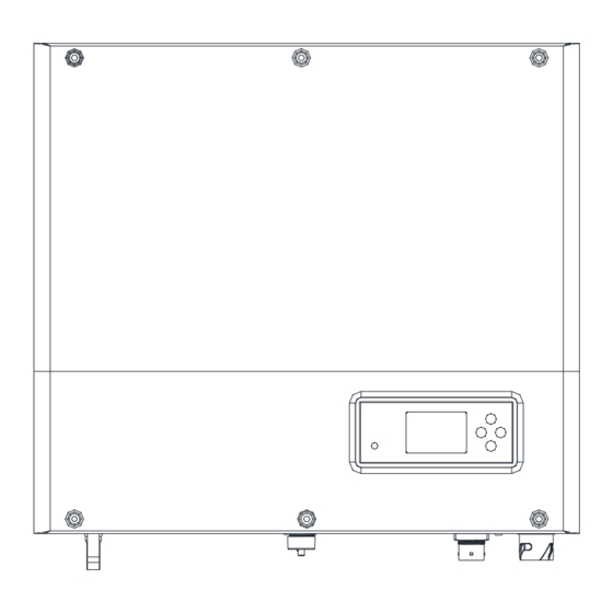
Overview
1
( ) Front panel
1
(2) Dual-color LED
(6) Heat sink
(7) Battery connector
(11) AC grid connector
(12) RSD (rapid shutdown device)
Note:
1. Only three-phase meter supports current direction detection.
2. Pin definition of the RJ45 connector is described later in this guide.
Note:
1.The information in this document is subject to change without notice due to product upgrades or customer feedback. All information and
suggestions in this document do not constitute a warranty of any kind, express or implied. Growatt reserves all rights for final explanation.
2. This document is for quick installation guidance only. For details, please refer to the User Manual.
3. Machine damage caused by failure to follow the instructions is not covered under any warranty.
2
Installation
.
System overview
AC coupled Inverter
Battery
Electrical Grid
AC
Breaker
Sensor
≥15m
Electric meter
2.2
Wall mounting
2
3
4
Note:
When installing the AC-coupled system, you need to consider the position of the battery
and the inverter.
2.1
Installation requirements
Grid
EPS
Breaker
AC
EPS
Breaker
Load
Load
SPA 4000-10000TL3 BH-UP Quick Guide
5
6
(3) LCD screen
(4) Push button
(8) USB port
(9) Dry contact port
(13) Ventilation valve
(14) Grounding screw
≥300
≥300
≥300
≥300
7
8 9 10 11 12 13 1415
(5) Inductor placing area
(10) NC (not connected)
(15) EPS output connector
505
472
16.5
Note:
Caution! When drilling holes, avoid
the water pipes and power cables
buried in the wall.
Unit: mm
198
Advertisement

Related Manuals for Growatt SPA 4000-10000TL3 BH-UP


Summary of Contents for Growatt SPA 4000-10000TL3 BH-UP
- Page 1 1.The information in this document is subject to change without notice due to product upgrades or customer feedback. All information and suggestions in this document do not constitute a warranty of any kind, express or implied. Growatt reserves all rights for final explanation.
- Page 2 Installing the communication module Follow the installation steps: 1. Remove the USB waterproof cover. 2. Plug in the communication module. Connecting cables Please prepare the cables before connecting as follows. Number Cable name Type Recommend specification Note: Grounding wire A multi-core yellow-green copper wire Wire diameter>AWG10 Make sure all switches are Two or three different color multi-core...
- Page 3 DC connection 3.3.1 Assembling the battery input cables Positive connector Positive metal terminal 8-10 mm Negative connector 8-10 mm Ensure that the cable cannot be pulled out Pull the battery cable back gently to check that Negative metal terminal from the terminal after crimping. they are connected securely.
- Page 4 RCD between the inverter and the grid, you are advised to install a type A RCD with a rating of 300 mA. Service and contact Shenzhen Growatt New Energy Co., Ltd. 4-13/F, Building A, Sino-German (Europe) Industrial Park, Hangcheng Blvd, Bao'an District, Shenzhen, China +86 755 2747 1942 service@ginverter.com...
Need help?
Do you have a question about the SPA 4000-10000TL3 BH-UP and is the answer not in the manual?
Questions and answers