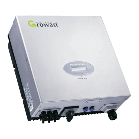
Growatt 1500 Installation & Operation Manual
Hide thumbs
Also See for Growatt 1500:
- Installation & operation manual (28 pages) ,
- User manual (22 pages) ,
- Troubleshooting manual (11 pages)
Advertisement
Table of Contents
Advertisement
Table of Contents

Summary of Contents for Growatt Growatt 1500
- Page 1 GROWATT NEW ENERGY CO.,LTD service@ginverter.com GR - UM - 001 - 07...
-
Page 2: Table Of Contents
Content Design Overview Congratulations on choosing our Grid PV Inverter, Our Grid PV Inverter are a highly reliable products due to their innovative design and perfect quality control. Such inverters are used in high demand, grid-linked PV systems. This manual contains important information regarding installation and safe operation of this unit. -
Page 3: Installation
Installation Bottom Overview 2.1 Installation manual Do not remove the casing. Inverter contains no user serviceable parts. Refer servicing to qualified service personal. All wiring and electrical installation should be conducted by a qualified service personnel and must meet national requirements of AS/NZS 3000. Both AC and DC voltage sources are terminated inside the PV Inverter. -
Page 4: Fixed On The Wall
AWG no. _(mm) Insert safety-lock screws to the bottom leg to secure the inverter (image 3). Check the secure mounting of the PV-Inverter by trying to raise it from the Growatt 1500-3000 2.05 3.332 bottom. The PV-Inverter should remain firmly attached. -
Page 5: Checking
Make sure the maximum open circuit voltage (Voc) Germany // 1 of each PV string is less than 580 VDC for Growatt 4000, Growatt 4400, Growatt 5000, Sungold 5000,less than 500 VDC for Growatt 2000, UK_G83 // 2... -
Page 6: System Diagram
When you need to select any of these countries, you can Double knock to enter the next interface. Here we select Italy as an example, as Fig 2-5-3. Note: If you have selected and confirmed an unwanted country neglectful, please contact Growatt for specific software to clear and reset again. Fig 2-5-3 2.5.2 Commissioning... -
Page 7: Modes Of Operation
3.2 Fault mode Connection system : This “interface” between Utility and PV-Inverter may consist of electrical breaker, fuse and connecting terminals. To comply with local safety standards and codes, the connection system should be The internal intelligent controller can continuously monitor and adjust the system designed and implemented by a qualified technician. - Page 8 The second line of LCD Starting-up display sequence: SerNo CYCLE DISPLAY DISPLAY TIME/S REMARK Once the PV power is sufficient, Inverter displays information as shown in the flow chart as follow: Etoday: xx.x KWh The energy today SerNo: xxxxxxxx Module: xxxxxxxxx FW Version: x.x.x Connect in xxS Connect OK...
-
Page 9: Inverter Status
Inverter Status When the LCD is bright: Inverter is designed to be user-friendly; therefore, the status of the Inverter can be Knock to make it display next information or change the set situation. easily understood by reading the information shown on the front panel display. All Double knock make the display stand for 30 second on 1-5. -
Page 10: Communications
Communication Trouble Shooting In most situations, the Inverter requires very little service. However, if Inverter is not 5.1 Communications software instructions able to work perfectly, please refer to the following instructions before calling your local dealer. Should any problems arise, the LED on the front panel will be red and the LCD displays the relevant information. - Page 11 Specifications Growatt4000 Growatt4400 Growatt5000 Growatt1500 Growatt2000 Growatt3000 Input Data Input Data Max. DC power 1800W 2300W 3200W Max. DC power 4200W 4600W 5000W/5200W 450V 500V 500V 580V 580V 580V Max. DC voltage Max. DC voltage PV voltage range 100V-450V 100V-500V 100V-500V PV voltage range 100V-580V...
- Page 12 Sungold 1500 Sungold 2000 Sungold 3000 Sungold 5000 Input Data 1800W 2300W 3200W 5200W Max. DC power Max. DC voltage 450V 500V 500V 580V PV voltage range 100V-450V 100V-500V 100V-500V 100V-580V MPP voltage range 175V-450V 195V-450V 250V-450V 250V-500V Number of MPP trackers/ 1 / 1 1 / 2 1 / 2...


Need help?
Do you have a question about the Growatt 1500 and is the answer not in the manual?
Questions and answers