Table of Contents
Advertisement
Quick Links
Advertisement
Table of Contents

Subscribe to Our Youtube Channel
Related Manuals for LEMKEN 9 Z10


Summary of Contents for LEMKEN 9 Z10
- Page 1 Operating Instructions Seeding Combinations Compact-Solitair 9 Z10 - EN - Item no. 17510464 02/08.22 LEMKEN GmbH & Co. KG Weseler Straße 5, D-46519 Alpen Telephone (0 28 02) 81-0, Fax (0 28 02) 81-220 E-mail: lemken@lemken.com, Internet: http://www.lemken.com...
- Page 3 However, this brief instruction is not a substitute for thorough study of the operating instructions. These operating instructions will help to familiarise you with the LEMKEN GmbH & Co. KG device and the options available for using it.
- Page 4 Remember that you should only use genuine LEMKEN spare parts. Reproduction parts have a negative influence on the function of the device, have a shorter ser- vice life and present risks and hazards that cannot be estimated by LEMKEN GmbH & Co. KG. They also increase the maintenance costs.
-
Page 5: Table Of Contents
Contents CONTENTS Contents ........................... 3 General information ....................13 Liability ......................... 13 Guarantee ........................13 Copyright ........................14 Optional accessories ....................14 Symbols used in the Operating Instructions ............15 Hazard classes ......................15 Information........................16 Environmental protection ................... 16 Indication of passages .................... - Page 6 Contents Operation on public highways ................... 28 3.9.1 Lighting system and identification ................28 3.9.2 Requirements of the tractor ..................28 3.9.3 Permissible lateral inclination during transportation ........... 29 3.9.4 Check before departure ..................... 30 3.9.5 Correct behaviour in road traffic ................30 3.10 Obligation of the operator ..................
- Page 7 Contents 5.2.18 Seed hopper ......................43 5.2.19 Sowing of seeds ..................... 43 5.2.20 Blower ........................43 5.2.21 Lighting system ...................... 43 5.2.22 Electronic control system ..................43 Fertiliser version ......................44 5.3.1 Container for fertiliser ....................44 5.3.2 Sowing system for seed or fertiliser ................44 Air brake ........................
- Page 8 Contents 6.10 Required hydraulic control units ................61 6.11 Actuation and adjustment of blower hydraulics ............62 6.11.1 Hydraulic equipment for the blower hydraulics ............62 6.11.2 Hydraulic system for the blower drive of the precision planter........ 63 6.12 Implement hydraulics ....................63 6.12.1 Signal socket ......................
- Page 9 Contents Lane width........................92 Blower speed ....................... 92 Electronic controller ....................93 Sowing shaft for seeds ....................93 9.10 Switching the sowing rollers on or off ..............94 9.10.1 Activating the sowing rollers ................... 95 9.10.2 Deactivating the sowing rollers ................96 9.11 Sowing shaft for fertiliser ...................
- Page 10 Contents 11.6 Knife tines with quick-coupling system ..............116 11.7 Power take-off ......................118 11.8 Side blade ........................118 11.8.1 Retracting the side blades ..................119 11.8.2 Extending the side blades ..................120 11.9 Side blade extension ....................121 11.10 Wheelmark eradicator ....................121 11.10.1 Relocation at the side ..................
- Page 11 Contents 11.21 Fertiliser version ....................... 135 11.22 Direct supply......................135 11.22.1 Using with precision planter ................135 11.23 Double control valve ....................137 11.23.1 Using with precision planter ................137 11.23.2 Using without precision planter ................. 139 11.24 Section width control ....................141 11.24.1 Shut-off slider - manual ..................
- Page 12 Contents 16.1 Turning at the headland .................... 155 16.1.1 Drive shaft ......................156 17 Tips for driving on public roads ................157 17.1 General ........................157 17.2 Brake system ......................157 17.3 Transport speed ......................157 17.4 Preparing for driving on public roads ..............157 17.4.1 Track markers ......................
- Page 13 Contents 20.4 Lubricants - transmission ..................168 20.4.1 Manual transmission .................... 168 20.4.2 Transmission pan ....................168 20.5 Manual transmission ....................169 20.5.1 Checking the oil ....................169 20.5.2 Oil change ......................170 20.5.3 Filling with oil ......................170 20.6 Transmission pan ...................... 171 20.6.1 Checking the fluidized grease ................
- Page 14 Contents 20.15 Scrapers ........................185 20.16 Cardan shaft ......................185 20.17 Cleaning the feeding units for seeds ............... 186 20.18 Cleaning the sowing units for fertiliser..............187 20.18.1 Check the sowing rollers ................... 189 20.19 Tightening torques ....................190 20.19.1 General information ...................
-
Page 15: General Information
Co. KG, in particular Section IX, shall apply. Liability. In line with the dimensions cited in these conditions the LEMKEN GmbH & Co. KG shall not be held liable for any personal or material damage, when such damage is caused by one or more of the following reasons: •... -
Page 16: Copyright
Infringements will result in a claim for damages. Optional accessories LEMKEN implements may be equipped with various accessories. The operating instructions below describe both series components and optional accessories. Please note: These accessories will vary depending on the type of equipment. -
Page 17: Symbols Used In The Operating Instructions
Symbols used in the Operating Instructions SYMBOLS USED IN THE OPERATING INSTRUCTIONS Hazard classes The following symbols are used in the Operating Instructions for particularly im- portant information: DANGER Denotes an imminent hazard with high risk, which will result in death or severe physical injury, if not avoided. -
Page 18: Information
Symbols used in the Operating Instructions Information Denotes special user tips and other particularly useful or important information for operation and efficient utilisation. Environmental protection Indication of special recycling and environmental protection measures. Indication of passages The following symbols are used for particular passages in the operating instruc- tions: −... -
Page 19: Safety Measures And Precautions
Safety measures and precautions SAFETY MEASURES AND PRECAUTIONS General safety instructions for the operator are specified in the chapter entitled «Safety measures and precautions». At the start of some main chapters the safety instructions, which refer to all work to be carried out in this chapter, are listed to- gether. -
Page 20: Safety Devices On The Device
Safety measures and precautions Safety devices on the device The device is equipped with special safety devices for the protection of the opera- tor and the device. − Always keep all safety devices in working order. Lighting system Stand Wheel chocks Safety and warning signs 3.4.1 General information The implement features all equipment... -
Page 21: Meaning Of Warning Signs
Safety measures and precautions 3.4.2 Meaning of warning signs − Please familiarise yourself with the meaning of the warning signs. The following explanations provide detailed information. Please read and observe the operating in- structions and safety instructions before starting up the implement for the first time. Before carrying out maintenance or repair work, switch off the engine and remove key. - Page 22 Safety measures and precautions Risk of crushing Do not ride on the platform of the imple- ment. Before uncoupling or parking the imple- ment, secure it with wheel chocks. Do not touch any moving implement parts. Wait until they have come to a standstill.
- Page 23 Safety measures and precautions Keep a sufficient distance away from elec- tric high-voltage lines. Hot surfaces Do not touch any moving machine parts. Wait until they have come to a standstill.
-
Page 24: Meaning Of Other Symbols
Safety measures and precautions 3.4.3 Meaning of other symbols. Lubricate and service implement in ac- cordance with maintenance chart. Connecting the cardan shaft The joints must be arranged at the same angle with respect to one another. Connecting the hydraulic hoses P2 / T2 •... -
Page 25: Overview Of The Position Of Warning Symbols
Safety measures and precautions Overview of blower speeds 3.4.4 Overview of the position of warning symbols... -
Page 26: Special Safety Instructions
Safety measures and precautions Special safety instructions Risk of injury due to non-observance of the currently valid occupational safety guidelines If the currently valid occupational safety guidelines are bypassed WARNING or safety equipment is rendered unusable when handling the de- vice, there is a risk of injury. - Page 27 Safety measures and precautions Risk of injury when freeing casualties When rescuing people trapped or injured by the device, there is a risk of additional serious injury to the casualty if the hydraulic con- nections were not connected according to their colour coding as described in the section entitled "Required hydraulic equipment".
-
Page 28: Hazardous Areas
Safety measures and precautions Hazardous areas Moving hazardous area WARNING The implement's hazardous area moves as the implement is op- erated! During implement operation, there must be nobody in front of the actual hazardous area, as the hazardous area moves with the im- plement. -
Page 29: Residual Risks
Safety measures and precautions Residual risks Residual risks are particular hazards which occur when handling the device and which cannot be eliminated despite a design in accordance with safety require- ments. Residual risks are not usually obvious and may be the source of a potential injury or health hazard. -
Page 30: Applicable Rules And Regulations
Safety measures and precautions Applicable rules and regulations The applicable rules which must be observed during operation of the device are listed below: • Observe the currently valid national highway code! • Observe the currently valid national laws and regulations for occupational safe- •... -
Page 31: Permissible Lateral Inclination During Transportation
Safety measures and precautions Risk of accidents due to inadequate braking deceleration In the event of insufficient braking deceleration, the combination of tractor and implement will be unable to be braked or not be braked quickly enough. This may result in a rear-end collision, and DANGER the driver or other road users may be injured or killed. -
Page 32: Check Before Departure
Safety measures and precautions 3.9.4 Check before departure − Check function of implement brakes before driving off. − Before driving with the implement raised, lock the control lever, otherwise it may drop and the implement may be unintentionally lowered. − Check that the fold-out safety device for the side parts is locked correctly. −... -
Page 33: Obligation Of The Operator
Safety measures and precautions 3.10 Obligation of the operator − Before switching on the device, read the operating instructions. − Follow the safety instructions! − Wear appropriate protective clothing when carrying out any work on the device. Protective clothing must be tight-fitting! −... -
Page 34: Operating The Device Safely
Safety measures and precautions 3.11 Operating the device safely 3.11.1 General information − Before starting work, familiarise yourself with all equipment and actuating ele- ments as well as their functions. − Do not operate the device until all protective devices have been attached and are in the safety position. -
Page 35: Personnel Selection And Qualifications
Safety measures and precautions In the wider operating range of the device there is a risk of injury, e.g. from ejected stones. − Before actuating hydraulic equipment (such as flap devices), ensure that there is nobody in the flap area. Risk crushing and/or shearing by remote power op- erated parts. -
Page 36: Hydraulic System
Safety measures and precautions 3.11.3 Hydraulic system • The hydraulic system is under high pressure. • When connecting hydraulic cylinders and motors, ensure that the specified hy- draulic hose connection is used. • When connecting the hydraulic hoses to the tractor hydraulics, make sure that the hydraulic system is depressurised on both the tractor and the implement. -
Page 37: Power Take-Off Operation
Safety measures and precautions 3.11.4 Power take-off operation • Only cardan shafts specified by the manufacturer may be used. • The protective tube and the protective funnel for the cardan shaft, along with the power take-off guard - on the implement side too - must be in place and must be in good condition. - Page 38 Safety measures and precautions • The cleaning, lubrication or adjustment of the implement driven by the power take-off or the cardan shaft may only be performed when the power take-off and the engine are switched off and the ignition key is removed. •...
-
Page 39: Handing Over The Device
Handing over the device HANDING OVER THE DEVICE − As soon as the device is delivered, ensure that it corresponds with the order package. − Also check the type and completeness of any supplied accessories. When the device is handed over, your dealer will explain how it works. −... -
Page 40: Layout And Description
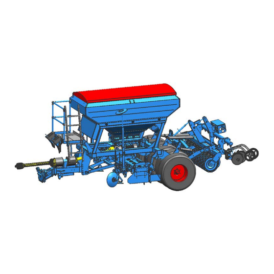
Layout and description LAYOUT AND DESCRIPTION Overview... - Page 41 Layout and description Drawbar 12 Seeding bar / OptiDisc double disk coulter Feeding disk 13 Sowing harrow (no diagram) Track loosener 14 Pulse wheel Track markers 15 Advance marking Rotary harrow 16 Ascent/platform Side shield 17 Container for seeds Levelling bar 18 Feeding Tyre packer 19 Blower...
-
Page 42: Description
Layout and description Description 5.2.1 Drawbar The drawbar corresponds to the chosen category as per ISO 730, either 3N or 3. Drawbar L2/Z3 corresponds to category 3N. Drawbar L3/Z3 corresponds to category 3. 5.2.2 Feed discs The feed disc prevents a damn formation and thus facilitates a precise next run. 5.2.3 Wheel track eliminators The wheel track eliminators are placed in front of the tilling device. -
Page 43: Side Blades
Layout and description 5.2.7 Side blades The height-adjustable side blades (1) and the extensions (2) prevent the outer tines from building up ridges. 5.2.8 Levelling bar The levelling bar ensures an even levelling of the ground. The rotary harrow can be equipped with a levelling bar: •... -
Page 44: Harrow Tyre Packer
Layout and description 5.2.10 Harrow tyre packer In conjunction with the coupling frame, the tyre packer can be equipped with a harrow. The harrow smooths the accumulated soil in the spaces between the individual tyres. 5.2.11 Coupling frame The implement can be equipped with a coupling frame. The coupling frame has a three-point interface, Category 2 or 3N according to ISO 730, which is provided for the attachment of a precision planter. -
Page 45: Pulse Wheel
Layout and description 5.2.15 Pulse wheel The pulse wheel is used to feed seeds at a rate that is relative to the vehicle speed. 5.2.16 Advance marking The advance marking is used to mark lanes for the tractor. 5.2.17 Ascent/platform The platform can be accessed via the ascent. -
Page 46: Fertiliser Version
Layout and description Fertiliser version 5.3.1 Container for fertiliser The container for fertiliser can hold 3500 litre. 5.3.2 Sowing system for seed or fertiliser Implement is equipped with a sewing system that is capable of handling fertiliser. The system is set up for seeds at delivery. A conversion of the sowing system is necessary for spreading fertiliser. -
Page 47: Air Brake
Layout and description Air brake Danger due to poor air brake maintenance WARNING A poorly maintained brake system has little or no braking effect. This means long braking distances, rear-ending other vehicles or even the tractor falling over. − Make sure the system is maintained regularly. −... - Page 48 Layout and description • Brake force regulator (4) • Filter (5) • Brake cylinder (6) • Brake cable for parking brake (7) • Brake lever (8)
-
Page 49: Description Of Functions
Layout and description 5.4.2 Description of functions The air brake system consists of the following units: • Parking brake • Operational brake • Tear-off brake The individual brake functions are activated according to when the brake cylinder is actuated. Parking brake The parking brake prevents rolling away. - Page 50 Layout and description Operational brake A compressed air supply from the tractor is required to operate the operational brake. If the device's brake lines are connected to the tractor, the device's air brake sys- tem is supplied with compressed air via the red brake coupling. When the tractor's hand brake or foot brake is pressed, the device begins braking.
- Page 51 Layout and description Disconnecting the brake lines Before removing the device, prevent it from rolling away using the parking brake and chocks. If the brake lines are disconnected from the tractor, the system automatically brakes with the operational pressure of the compressed air container. Shunting −...
-
Page 52: Hydraulic Braking System
Layout and description Hydraulic braking system Danger due to poor air brake maintenance WARNING A poorly maintained brake system has little or no braking effect. This means long braking distances, rear-ending other vehicles or even the tractor falling over. − Make sure the system is maintained regularly. −... -
Page 53: Description Of Functions
Layout and description 5.5.2 Description of functions The hydraulic brake system consists of the following units: • Parking brake • Operational brake • Tear-off brake Parking brake The parking brake prevents rolling away. − Move the lever (1) in the direction of travel to activate the parking brake. -
Page 54: Preparation Of The Tractor
Preparation of the tractor PREPARATION OF THE TRACTOR Tyres Ensure that all are at the manufacturer's recommended pressures and that left and right hand side tyre pressures are identical. (See manufacturer's instructions)! Lift Rods Adjust lift rods to equal length by means of the adjuster device. (See tractor manu- facturer's instructions) Check Chains or Sway Blocks of the Three Point Linkage Check chains or sway blocks must be adjusted so that the lower links of the trac-... -
Page 55: Brake Force Regulator
Preparation of the tractor 6.4.2 Brake force regulator The braking force is adapted to the weight of the implement using the brake force regulator. The lever (1) of the brake force regulator (2) is rotated accordingly for the adjust- ment. The arrow (3) indicates the setting to which the braking force is active. -
Page 56: Cardan Shaft
Preparation of the tractor Cardan shaft 6.5.1 Inspect and mount cardan shaft The wide angle joint (1) must always be fitted to the implement. See also «Attaching, page 80». The labelling and direction of installation on the protection tube differs. When the implement is coupled, a check must be carried out to determine wheth- er the length of the cardan shaft is correct. -
Page 57: Cardan Shaft Shortening
Preparation of the tractor 6.5.2 Cardan shaft shortening − Pull the two cardan shaft halves apart. − Hold the two cardan shaft halves against one another with the shortest possible gap between the tractor and the imple- ment. − On the outer protective tube, mark the length you need to cut off. - Page 58 Preparation of the tractor − Hold the cut section of the inner protec- tive tube (2) over the inner profile tube (9) and cut off the inner profile tube (9) at right angles. − Debur and clean the outer and inner pro- file tubes.
-
Page 59: Lower Control Link Coupling
Preparation of the tractor Lower control link coupling Danger of injury through breakage of mounting studs WARNING A lower control link coupling with an undersize category may cause the mounting studs (2) to break. When tractors with a large output are used, the mounting studs (2) may break. -
Page 60: Hydraulic System
Preparation of the tractor Hydraulic system 6.7.1 Transport Lowering the three-point linkage CAUTION The implement may be damaged if the three-point linkage of the tractor is lowered due to an incorrect setting or operation. − For transport, always switch the hydraulic system of the three- point linkage of the tractor to "position control". -
Page 61: Power Supply
Preparation of the tractor Power supply A 12 V supply voltage is required for the electronic control system. Voltages above and below this value may cause malfunctions and, under certain circumstances, this may destroy the electrical equipment. The battery mounting kit (1) with 40 A fuse (2) and plug connector (3) with locking clamp (4) supplied is used for the connec- tion to the tractor battery. -
Page 62: Required Power Sockets
Preparation of the tractor − Connect the plug (9) to the plug con- nector in the battery mounting kit. − Then lock the plug (9) using the locking clamp. When the implement is uncoupled: − Disconnect the cables. − Protect the cable on the implement against moisture. -
Page 63: Required Hydraulic Control Units
Preparation of the tractor 6.10 Required hydraulic control units To activate the individual hydraulic units specified below, the tractor must be equipped with the following control units: Controller Double ac- Single-acting Pressure- ting control Colour Code control unit less return unit Setup Forward... -
Page 64: Actuation And Adjustment Of Blower Hydraulics
Preparation of the tractor 6.11 Actuation and adjustment of blower hydraulics WARNING The hydraulic lines for the blower are used to supply important functions with oil and to actuate the safety valves. − Always connect the hydraulic lines for the blower to the tractor. The hydraulic line to the blower's hydraulic motor is also used to supply the follow- ing valves with oil pressure: •... -
Page 65: Hydraulic System For The Blower Drive Of The Precision Planter
Preparation of the tractor 6.11.2 Hydraulic system for the blower drive of the precision planter The blower drive for the precision planter can be controlled via the following hy- draulic equipment: • Additional single-acting control unit of the tractor with pressure-less return or •... -
Page 66: Preparations On Implement
The interface for the fertiliser hoses is at the end of the filling pipes (1) on the three- point linkage. Due to the variety of designs, the distribu- tors for fertiliser are not included. You can purchase different filling pipes and distribu- tors from LEMKEN. -
Page 67: Scope Of Delivery
Preparations on implement 7.2.2 Scope of delivery The following parts are included in the scope of delivery for the conversion of the sowing system: Hexagon screw M6x22.5 (31) Hexagon screw M6x10 (32) Washer (33) Hose clip (34) Hose clamp (35) Hose (36) Emitter (37) Holder... -
Page 68: Removing The Sowing System For Seeds
Preparations on implement 7.2.3 Removing the sowing system for seeds − Remove the calibration tray (1) from its holder. − Change the position of the lever (2) for the adjustment of the bottom gates. − Remove the securing pin (3). −... - Page 69 Preparations on implement − Remove the sheet metal panel (19). − Loosen the stop screws (21), see "Switching off the sowing rollers". − Remove the cotter pin (23). − Remove the washer (22). − Pull the sowing shaft (20) with the mounted gearwheel (25), the washer and the bearing (26) out of the sowing system.
-
Page 70: Mounting The Sowing System For Fertiliser
Preparations on implement 7.2.4 Mounting the sowing system for fertiliser When spreading fertiliser, a large amount of fertiliser dust can develop on the sowing system. Using special dust caps, the fertiliser dust is guided to the ground and the surrounding components are protected from large deposits. −... - Page 71 Preparations on implement − Install washer (33) and the sowing roller (42) in the additional sowing unit as pre- viously described. − Engage the sowing roller (42) using the stop screw (46), see "Engaging the sow- ing rollers". − Install the sheet metal panel (41). −...
- Page 72 Preparations on implement − Install the chain (9). − Tighten the spring (7) of the chain ten- sioner (8). − Install the washers (not shown) behind the chain guard (6). − Install the chain guard (6) using screw (4)+(5) and washer. −...
- Page 73 Preparations on implement − Install the rear dust cap (40) using the screws (32). − Install the hose (36). − Secure the hose (36) using the hose clip (34). − Guide the hoses (36) along the sowing system to the ground. −...
-
Page 74: Removing The Sowing System For Fertiliser
Preparations on implement 7.2.5 Removing the sowing system for fertiliser − Remove the calibration tray (1) from its holder. − Change the position of the lever (2) for the adjustment of the bottom gates. − Remove the folding pin (3). −... - Page 75 Preparations on implement − Loosen the hose clip (34) − Remove the hose (36). − Remove the screws (31). − Loosen the screw (10). − Remove the front dust cap (39). − Remove the cable (15). − Remove the nut (13)+(14) with washer. −...
- Page 76 Preparations on implement − Remove the cotter pin (23). − Remove the washer (22). − Pull the sowing shaft (20) with the mounted gearwheel (25), the washer and the bearing (26) out of the sowing system. − Remove the bearing (24). −...
-
Page 77: Installing The Sowing System For Seeds
Preparations on implement 7.2.6 Installing the sowing system for seeds − Guide the sowing shaft (20) with the mounted gearwheel (25), the washer and the bearing (26) to the middle of the first sowing unit. − Install the sowing rollers (25) separated by washers (26) as shown. - Page 78 Preparations on implement − Install sowing rollers (25) separated by washers (26) in the additional sowing unit as previously described. − Engage the desired sowing roller (25) using the stop screw (21), see "Engag- ing the sowing rollers". − Install the sheet metal panel (19). −...
- Page 79 Preparations on implement − Install the chain (9). − Tighten the spring (7) of the chain ten- sioner (8). − Install the washers (not shown) behind the chain guard (6). − Install the chain guard (6) using screw (4)+(5) and washer. −...
-
Page 80: Checking The Bottom Gates
Preparations on implement 7.2.7 Checking the bottom gates − Keep the distance of the bottom gate (2) to the sowing roller (1) as small as pos- sible. But the sowing roller (1) may not touch the bottom gate (2). − Check the clearance by manually rotat- ing the sowing roller (1). -
Page 81: Coupling And Uncoupling
Coupling and uncoupling COUPLING AND UNCOUPLING Danger to life due to unsecured connection between lower link and drawbar If the connection between lower link and drawbar is not secured, DANGER the pintle of the drawbar may slip out. As a result, other road users may be injured or killed while the im- plement is being transported. -
Page 82: Attaching
Coupling and uncoupling Attaching − Set the tractor hydraulics of the three- point power linkage for the attachment of the device to position control. − Reverse the tractor to the implement so that it is positioned straight in front of the implement and the grab hooks of the lower links can be coupled with the drawbar (3). - Page 83 Coupling and uncoupling − Connect the hydraulic hoses to the trac- tor as specified in the table in the "Re- quired hydraulic equipment" section. − Connect the electric cables to the tractor as specified in the table in the "Required hydraulic equipment"...
- Page 84 Coupling and uncoupling In conjunction with hydraulic brake system: − Release the parking brake (11) and swing it back completely. − Raise the implement entirely at the rear. See the operating instructions for the electronic controller. − Lock the control units of the tractor. −...
-
Page 85: Detaching
Coupling and uncoupling Detaching CAUTION − Only park the implement on firm and level ground. − Set the tractor hydraulics to position con- trol. − Release the pin (6) of the stand (7) and pull it out. − Lower the stand (7). −... - Page 86 Coupling and uncoupling − Take the wheel chocks (8) out of the holder (9) and secure the implement against rolling. − Disconnect the brake hoses. In conjunction with an air brake system: − Adjust the brake force regulator (10) . −...
- Page 87 Coupling and uncoupling − Disconnect the electric cables. Close the shut off valves (12) and (13). − Move the activation lever of the control unit in the floating position to depressur- ise the hydraulic hoses. − Disconnect the hydraulic hoses and slide the protective caps open.
-
Page 88: Seeding Bar
Coupling and uncoupling Seeding bar 8.3.1 Attaching − Remove the grab hooks (7). − Remove the harrow (8) for the tyre packer (option). − Reverse the device to the seeding bar so that it is positioned straight in front of the seeding bar and the grab hooks of the lower links (5) can be coupled with the drawbar. - Page 89 Coupling and uncoupling for use without roller: − Remove the stands on both sides of the seeding bar.
-
Page 90: Detaching
Coupling and uncoupling 8.3.2 Detaching for use without roller: − Remove the stands (1) on both sides of the seeding bar. − Lower the seeding bar to the ground. − Remove the cable from the holder. − Remove the hydraulic lines from the holder. -
Page 91: Precision Planter
Coupling and uncoupling Precision planter 8.4.1 Attaching Observe the maximum load of the coupling frame, see «Technical data, page 161». − Position the grab hooks (7) according to the precision planter. − Mount the grab hooks (7) from the out- side to the coupling frame using two bolts and two nuts each. -
Page 92: Detaching
Coupling and uncoupling 8.4.2 Detaching − Lower the precision planter to the ground. − Remove the cable from the holder. − Remove the hydraulic lines from the holder. − Remove the hoses of the precision planter from the filling pipe. −... -
Page 93: Use
General Instructions Before the first use it is recommendable - with fully lowered implement - to carry out the following adjustments at the farm and to make familiar with the machine and its functions. Afterwards only few adjustment corrections have to be carried out in the field. -
Page 94: Optidisc Double Disc Coulters
OptiDisc double disc coulters The OptiDisc double disc coulters (1) with pressure roller (2) are mounted on rubber and parallel to each other. The height of the frame tube (3) above each positioning device must be such that the underside of the frame tube (3) is approx. -
Page 95: Electronic Controller
Electronic controller Using the electronic controller, the device is adjusted using the control terminal (1) and an unscrewing test carried out. See the operating instructions for the electronic controller. Sowing shaft for seeds The sowing shaft (1) has 6 sowing rollers for each sowing system: •... -
Page 96: Switching The Sowing Rollers On Or Off
9.10 Switching the sowing rollers on or off Danger of injury due to rotating sowing shaft WARNING There is a danger of injury when the operating terminal is switched on and the sowing shaft is rotating. − Before working on the sowing rollers, always switch off the con- trol terminal of the electronic controller. -
Page 97: Activating The Sowing Rollers
9.10.1 Activating the sowing rollers A sowing roller is activated by screwing in the stop screw (3). When unscrewing the stop screw, make sure that it is always exactly screwed into the groove (6) of the sowing shaft (7) and located within the perimeter of the sowing roller. The stop screw must be screwed in far enough that it is still located within the perimeter of the sowing roller and not jammed with the sowing shaft (7). -
Page 98: Deactivating The Sowing Rollers
9.10.2 Deactivating the sowing rollers • Read and observe the general safety instructions and the CAUTION "Maintenance" safety instructions. • In the "Unscrewing Test" menu and when the pulse wheel is turned, the sowing rollers, sowing shaft, and agitator shaft turn as well. -
Page 99: Sowing Shaft For Fertiliser
9.11 Sowing shaft for fertiliser The sowing shaft (6) is fitted with 4 sowing rollers (10) per sowing system (8) which are separated by means of partition discs. In order to ensure even sowing, all sowing rollers need to be switched on. -
Page 100: Bottom Gate
9.13 Bottom gate Before filling the container with seed and fertiliser, the bottom gates need to be adjusted. 9.13.1 Adjusting the bottom gate for seed. The bottom gates in the sowing device for seed need to be brought into the following positions using the lever (3) as a function of the seeds used. -
Page 101: Adjusting The Bottom Gate For Fertiliser
9.13.2 Adjusting the bottom gate for fertiliser. The bottom gates in the sowing device for fertiliser need to be brought into position 1 using the lever (4).. No other positions are required for this at- tachment. -
Page 102: Unscrewing Test
9.14 Unscrewing test CAUTION − During the unscrewing test, watch out for the danger areas for rotating and oscillating components. The unscrewing test can be carried out once the seeding rollers and the bottom gates have been adjusted according to the seeding table. See the operating in- structions for the electronic controller. -
Page 103: Hopper
9.15 Hopper − Do not put small parts in the hopper – even when shunting, the agitator shaft can rotate. − Please observe the permissible filling quantities. To fill the hopper: − Unhook the rubber tensioner (1) from its holder. −... -
Page 104: Agitator Shafts
9.16 Agitator shafts 9.16.1 Agitator shaft in seed container The agitator shaft (1) in the seed container needs to be switched off for delicate seeds. − To do this, pull the securing pins (3) out of the drive gearwheel (2) of the agitator shaft (1). -
Page 105: Sequence Control
Sequence control SEQUENCE CONTROL − Only start the sequence control when no one is standing in the vicinity of the operating or swivelling range of the implement. WARNING To activate the sequence control, the sensor (1) is switched and the double-acting control unit is brought into position. This results in a series of actions that cannot necessarily be stopped. - Page 106 Sequence control When the double acting control unit is ac- tuated for raising and lowering the tilling device, sequence control is activated. In sequence, when the lever of the double acting control unit is kept in the pressure position • the tilling device is raised •...
- Page 107 Sequence control The actions performed as a consequence of activating the sequence control can be stopped as follows: • put the double-acting control unit in neu- tral • Press the EMERGENCY STOP switch (3) on the control terminal (4) The delay between raising the tilling device and raising the coulter bar or between low- ering the tilling device and lowering the coulter bar is configured using the control...
-
Page 108: Raising
Sequence control 10.1 Raising If you set the corresponding control unit for the sequence control towards "Rais- ing", the tilling device and the track marker are raised at almost the same time. The coulter bar (and the leading roller with mounted coulter bar – option) is raised. The coulter bar is raised until the preset position is reached. -
Page 109: Deactivating The Raising And Lowering Process
Sequence control 10.3 Deactivating the raising and lowering process DANGER Every time the dual-action controller is actuated, the track markers move in and out if they are not locked in the folded position or if they are not deactivated. The following devices can be deactivated using the operation terminal of the elec- tronic controller. -
Page 110: Adjustments
Adjustments ADJUSTMENTS Risk of accident when making adjustments When making any adjustments to the device, there are risks of crushing, cutting, clamping and striking your hands, feet and body on heavy and occasionally compressed and/or sharp-edged parts. • Always park implement on the ground. DANGER •... -
Page 111: Drive Shaft Monitoring
Adjustments 11.1 Drive shaft monitoring An electronic controller monitors the drive shaft. Monitoring is carried out via the speed sensor (1) and the control terminal of the electronic controller which is supplied with power from a distributor box. If an alarm is triggered, the PTO shaft of the tractor must be switched off immediate- ly and the cause of the fault eliminated. -
Page 112: Rotor Speeds
Adjustments 11.2.2 Rotor speeds The following rotor speeds are possible, depending on the power take-off speed: Variant 1 Variant 2 If the cardan shaft's overload coupling responds too quickly on non-stony ground, at a power take-off shaft speed of 540 rpm or 750 rpm, then the power take-off shaft speed of 1000 rpm with matching gear must be selected. - Page 113 Adjustments For a normal gearbox: Shifting lever (2) in position (3) = rotor speed 330 rpm with 1000-rpm power take- off speed. Shifting lever (2) in position (4) = rotor speed 440rpm with 1000-rpm take-off speed. For a slow gearbox: Shifting lever (2) in position (3) = rotor speed 330 rpm with 1000-rpm power take- off speed.
- Page 114 Adjustments Recommended working speed depending on rotor speed Rotor speed per minute The rotor speed can be changed using the shifting lever. The 1000 rpm power take-off speed should always be selected. If a power take-off speed of 540 rpm or 750 rpm is used, then the input torque increases by 85 % or by 33 % and it does so at the same power transfer.
-
Page 115: Horizontal Position
Adjustments 11.3 Horizontal position During work, the implement should be horizontal. The adjustment required to en- sure this is made by adjusting the length of the tractor's upper link. If the tractor's power take-off is at a downwards or upwards incline towards the rear instead of parallel with the ground, the implement must be adjusted using the tractor's upper link so that the gearbox input shaft, when lowered into the working position, is parallel with the power take-off. -
Page 116: Change In The Direction Of Rotation Of The Rotors
Adjustments 11.5 Change in the direction of rotation of the rotors The direction of rotation may only be changed when the tractor power take-off is switched off and the tractor engine is at a standstill. The direction of rotation of the rotors with quick-change tines can be changed by moving the gearbox (1) to the side. - Page 117 Adjustments − Carefully clean the area around the gearbox flange (2). − Remove all of the protective caps (3). − Undo all of the centring nuts (4) until they are flush with the stud (5). − Rotate the discs (6) by 180°. −...
-
Page 118: Knife Tines With Quick-Coupling System
Adjustments 11.6 Knife tines with quick-coupling system When the bar (2) is unlocked, it is easy to change the tines (1) manually as fol- lows; CAUTION The safety stirrup is under enormous spring tension. It may only be lifted back with a suitable tool such as a screwdriver. −... - Page 119 Adjustments New knife tines with quick-coupling system are mounted in the reverse order to the order described above. They are inserted into the tine carrier (4) and then pushed inwards. − Secure tines with the bar (2). − The bar (2) is locked by lifting back the safety stirrup (3).
-
Page 120: Power Take-Off
Adjustments 11.7 Power take-off The tractor's power take-off may not be switched on until the circular spike harrow has been lowered until it is only a few cen- timetres above the ground, and the side blades (1) prevent any penetration into the rotating tools. -
Page 121: Retracting The Side Blades
Adjustments 11.8.1 Retracting the side blades For road transportation, the side blades (2) of the 3 m and 3.5 m wide rotary har- rows are to be retracted to ensure that the maximum permissible transport width is not exceeded. − Remove the spring pin (7). −... -
Page 122: Extending The Side Blades
Adjustments 11.8.2 Extending the side blades Before the next work assignment and be- fore the tractor power take-off is switched on, the side blades (2) must be folded down as follows: − Remove the spring pin (7) and guide pin (6). -
Page 123: Side Blade Extension
Adjustments 11.9 Side blade extension − Bolt the side blade extensions (4) at the rear onto the side blades (2). After undoing the bolts (5) each side blade extension in the slots, under the washers (6), can be moved slightly forward or backward! The distance to the roller should be as small as possible. -
Page 124: Adjusting The Working Depth
Adjustments 11.10.2 Adjusting the working depth The wheelmark eradicators are set to ap- prox. 5 cm deeper than the bout of the tractor. Adjust the working depth of the wheelmark eradicator as follows: − Raise the implement to relieve the load- ing on the wheelmark eradicator (1). -
Page 125: Feed Discs
Adjustments 11.11 Feed discs The feed disc (1) prevents a damn formation and thus facilitates a precise next run. − Remove the pin (2). − Remove the feed disc (1) from the hold- er (3) for the transport position. − Remove the feed disc (1) from the hold- er (4) for the working position. -
Page 126: Levelling Bar
Adjustments 11.12 Levelling bar CAUTION Before adjusting the levelling bar, you must move the side shields to the working position. 11.12.1 Levelling bar - rear − Adjust the levelling bar (1) using the torque tube (2) so that the lower edge of the levelling bar is approx. -
Page 127: Double Disc Coulter
Adjustments 11.13 Double disc coulter The double disc coulters are fitted with strippers made from vulcanised material. Hard metal strippers are also available. 11.13.1 Strippers for double disc coulters The double disc coulters (1) are fitted with self-adjusting strippers (3). The individual stripper (3) is placed on the holder (4). -
Page 128: Drilling Depth Of Seeding Coulter
Adjustments 11.13.3 Drilling depth of seeding coulter The drilling depth is adjusted using the spindle. − Rotate the spindle in the clockwise direc- tion for a larger drilling depth. − Rotate the spindle anticlockwise for a smaller drilling depth. Implement with coupling frame −... -
Page 129: Coulter Pressure Depth Of Seeding Coulter
Adjustments Device with coupling frame and roller − Align the frame of the sowing rail over the upper linkage (1) horizontal to the device. The drilling depth is adjusted using the spindle (2). − Rotate the spindle in the clockwise direc- tion for a larger drilling depth. -
Page 130: Harrow
Adjustments 11.14 Harrow The harrow is swivel mounted with the seeding bar and can thus freely adapt to the contours of the ground. The harrow is limited by a stop. 11.14.1 Adjusting the contact angle The angle adjustment of the harrow (2) is adjusted using the spindle (1). -
Page 131: Track Markers
Adjustments 11.15 Track markers WARNING − Never stand in the folding range for the track marker. Track markers which are folded out and deactivated fold in when the control unit is actuated, even though they are deactivated. 11.15.1 General The track markers (1) are folded in and out using the dual-action control unit. -
Page 132: Unlocking The Track Marker
Adjustments 11.15.3 Unlocking the track marker The track marker must be unlocked before it can be actuated. − Remove the pin (4) with the securing pin from the locking position (4) of the track marker. − Fit the pin (4) into the stop position (3) of the track marker. -
Page 133: Lane Mode
Adjustments 11.16 Lane mode Lane mode (1) is used to switch off the sowing rows if lanes need to be created. The working width of the maintenance de- vice is entered in the input menu for the electronic controller. The lane rhythm re- quired is then calculated automatically. -
Page 134: Impulse Wheel
Adjustments 11.17 Impulse wheel CAUTION When the impulse wheel is rotated, the seed wheels, the seeding shaft and the agitator shaft are also rotated. Ensure that there is adequate safety clearance. The impulse wheel (1), which must be low- ered before using it on the land, is used to transmit the length or path signals to the electronic control system. -
Page 135: Blower
Adjustments 11.18 Blower The seeds and fertiliser are transported to the coulter using compressed air from the blower (1). The speed of the blower (1) is set with the oil quantity via the control unit of the trac- tor. The current speed is displayed via the control terminal of the electronic controller. -
Page 136: Control Unit Without Control Valve
Adjustments 11.19 Control unit without control valve The adjustment of the speed occurs via the control valve of the implement. − Open the control valve (1) completely right turning the setting wheel (2) to posi- tion 10. − Activate the control unit of the tractor for the drive of the blower. -
Page 137: Fertiliser Version
Adjustments 11.21 Fertiliser version The blower for the precision planter can be driven hydraulically via: • direct supply • double control valve Observe the additionally required oil quantity of the tractor for the precision plant- See also the operating manual of the precision planter. 11.22 Direct supply The separate hydraulic hose for the precision planner leads up to the interface of the implement. - Page 138 Adjustments Control unit with control valve The adjustment of the speed occurs via the control valve of the two control units, the control valve of the implement, and the control valve of the precision planter. − Open the control valve (1) completely right turning the setting wheel (2) to posi- tion 10.
-
Page 139: Double Control Valve
Adjustments 11.23 Double control valve Via the double control valve, the required quantity of oil of the implement and of the precision planner are set separately from each other. 11.23.1 Using with precision planter Control unit without control valve − Close the shut-off valve (3) as shown in the figure. - Page 140 Adjustments Control unit with control valve − Close the shut-off valve (3) as shown in the figure. − Open the control valve (1) completely by turning the setting wheel (2) to position − Open the control valve (2) completely by turning the setting wheel (2) to position −...
-
Page 141: Using Without Precision Planter
Adjustments 11.23.2 Using without precision planter Control unit without control valve − Open the shut-off valve (3) as shown in the figure. − Fully close the control valve (2). − Open the control valve of the tractor all the way. −... - Page 142 Adjustments Control unit with control valve − Open the shut-off valve (3) as shown in the figure. − Fully close the control valve (2). − Open the control valve of the tractor all the way. − Open the control valve (1) completely by turning the setting wheel to the left until the stop.
-
Page 143: Section Width Control
Adjustments 11.24 Section width control Depending on the working width of the implement, section widths can be switched off by closing the shut-off slider (1). 11.24.1 Shut-off slider - manual In order to switch the section width, move the shut-off slider (1) manually to the re- quired position. -
Page 144: Spreaders
Adjustments 11.25 Spreaders The spreaders (1) are fitted with screw-on spreader points (2) which facilitate easy inspection of the spreader. If required, individual spreader outlets can be sealed as follows using conical plugs: − Unscrew the spreader points. − Seal the required outlets with conical plugs. -
Page 145: Sowing Harrow
Adjustments 11.27 Sowing harrow CAUTION You must always guarantee that the pulse wheel (9) never comes into contact with the harrow during sowing. The sowing harrow is screwed onto the support (1). 11.27.1 Harrow adjustment The harrow position is adjusted using the pins (2) and (3). -
Page 146: Harrow Pressure
Adjustments 11.27.2 Harrow pressure The harrow pressure is adjusted by rotat- ing the springs (6) and and adjusting the plates (10). • High harrow pressure => adjust the springs in a clockwise direction • Low harrow pressure => adjust the springs in an anticlockwise direction The nut (7) of the screw (8) must be tight- ened in such a way that the springs (6) -
Page 147: Advance Marking
Adjustments 11.28 Advance marking 11.28.1 General The annular plate units are screwed onto the seeding rail frame using an addition- al holder to serve as an advance marker. The oil is supplied to the relevant hydraulic cylinder through an oil circuit for the blower hydraulic motor. -
Page 148: Depth Of Marking Slot
Adjustments 11.28.3 Depth of marking slot. The depth of the marking slot can be set by turning the spring (4). • Turning the spring clockwise => lower marking slot • Turning the spring anticlockwise => higher marking slot The screw (5) is used to press the plates (6) firmly against the spring so that they cannot be accidentally adjusted but can still be adjusted by hand. -
Page 149: Leading Roller
Adjustments 11.29 Leading roller The leading roller (1) is located behind the tyre packer (2). The seeding bar (3) is mounted on the leading roller (1) and can only be raised or lowered together with the leading roller. The ground pressure of the leading roller can be adjusted via the electronic control system and read on the pressure gauge (4). -
Page 150: Adjusting The Scrapers
Adjustments 11.30 Adjusting the scrapers The adjustable scrapers (1) for the size 500 rollers are adjusted using setting nuts (2) or eccentric nuts (3). − Adjust the setting nuts (2) for the toothed packer rollers using a 19 mm wrench and the eccentric nuts (3) using a 24 mm wrench. -
Page 151: Clearance Between Scraper And Roller Casing
Adjustments 11.31 Clearance between scraper and roller casing The clearance between the scraper (1) and the roller casing (5) must be set in line with the following schedule. The adjusting instructions apply to all toothed packer rollers, trapezoidal packer rollers and trapezoidal disk rollers. Heat-treated scraper (1) Plastic scraper (1) (must make contact with roller casing (5) -
Page 152: Seedtable
Seedtable SEEDTABLE... -
Page 153: Emptying The Seed Container
Emptying the seed container EMPTYING THE SEED CONTAINER The seed container can be emptied through the calibration tray or the spreader; small residual amounts are emptied into the calibration tray (1) while greater re- sidual amounts can be emptied through the individual spreaders. 13.1 Emptying through the calibration tray −... -
Page 154: Emptying With The Spreaders
Emptying the seed container 13.2 Emptying with the spreaders The seed container is emptied pneumatically using the blower. Alternatively, the seed container can be emptied through one or more of the spreaders as follows: − Remove the calibration tray from the holder. -
Page 155: Tyres
Tyres TYRES • When working on the tyres, make sure that the device is safely parked and secured against rolling away (chocks). CAUTION • Fitting tyres requires sufficient knowledge and proper fitting tools. • Repairs to tyres and wheels must only be carried out by special- ists with suitable fitting tools. -
Page 156: Working Lights
Working lights WORKING LIGHTS The working lights (1) are switched on and off from the input menu in the control ter- minal. The tractor's lights must be switched See the operating instructions for the elec- tronic control system. -
Page 157: Operation
Operation OPERATION 16.1 Turning at the headland DANGER Risk of damage to components If the implement is not fully raised, there is a danger that compo- nents may be damaged during an improper turn at the headland. Before turning at the headland the implement must be completely raised before turning-in to avoid any damage to the implement. -
Page 158: Drive Shaft
Operation 16.1.1 Drive shaft CAUTION Damage to drive shaft − Always observe the permitted angle. − Switch off the drive shaft during the turning at the headland. Maximum permissible angle (°): With wide angle joint Working angle For short period operation with reduced power Stationary... -
Page 159: Tips For Driving On Public Roads
Tips for driving on public roads TIPS FOR DRIVING ON PUBLIC ROADS 17.1 General If the implement is to be transported on public roads, it needs the officially re- quired lighting system, identification and equipment. The local rules and regula- tions pertaining to the use of public roads must be complied with. -
Page 160: Track Markers
Tips for driving on public roads 17.4.1 Track markers − Remove the pin (4) with the folding pin from the stop position (2) of the track marker (1). − Fit the pin (1) in the locking position (4) of the track marker (1). −... -
Page 161: Pulse Wheel
Tips for driving on public roads 17.4.4 Pulse wheel − Swivel the wheel arm (1) up. − Secure the wheel arm (1) with the pin (2). 17.4.5 Operation terminal The implement may only be transported with the operation terminal switched off. −... -
Page 162: Lighting System
Tips for driving on public roads 17.4.7 Lighting system − Check the front lighting system (1) for proper function. − Check the rear lighting system (2) for proper function. 17.4.8 Sowing harrow The outer tines must be shifted inwards on the frame to comply with the permitted transport width. -
Page 163: Technical Data
Technical data TECHNICAL DATA Compact-Solitair 9 Z Number of seeding coulters for 125 mm row spacing Number of seeding coulters for 167 mm row spacing Seed container [ l ] 3,500 3,500 420/65 R20 XM108 125 A8 Tyres 405/70-20 AS-504 147 A8 Length approx. -
Page 164: Switching Off The Device
Switching off the device SWITCHING OFF THE DEVICE 19.1 Shutting down the device in an emergency − In an emergency shut down the device via the tractor. − Switch the tractor engine off. − Remove the ignition key. Damage caused by improper storage of the device If incorrectly or improperly stored, the device may be damaged, CAUTION e.g. -
Page 165: Maintenance And Repairs
Maintenance and repairs MAINTENANCE AND REPAIRS 20.1 Special safety instructions 20.1.1 General Risk of injury when carrying out maintenance and repair work There is always the risk of injury when carrying out maintenance and repair work. WARNING − Use suitable tools, suitable climbing aids, platforms and support elements. -
Page 166: Immobilise The Implement For Maintenance And Repairs
Maintenance and repairs 20.1.4 Immobilise the implement for maintenance and repairs Risk of accidents when tractor starts up Injuries may occur if the tractor starts moving during maintenance and repair work. − Switch off the tractor engine before carrying out any work on the WARNING implement. -
Page 167: Working Under The Raised Device
Maintenance and repairs 20.1.7 Working under the raised device Risk of accident due to lowering and extending of compo- nents and devices It is extremely dangerous to work under raised or next to retracted WARNING components and devices. • Always secure the tractor to prevent it from rolling away. Re- move the ignition key and secure the tractor to prevent it from being started up by unauthorised persons. -
Page 168: Environmental Protection
Maintenance and repairs Risk of accident due to tool slipping off If applying a large force, e.g. when loosening bolts, the tool may WARNING slip off. This may result in hand injuries on sharp-edged parts. − Avoid applying a large force by using suitable auxiliary equip- ment (e.g. -
Page 169: Lubrication
Maintenance and repairs 20.3 Lubrication Eye injuries due to grease WARNING When lubricating the lubrication points, grease can escape be- tween components at high pressure and cause injury to the eyes. In case of injury, seek medical attention immediately. − Wear protective clothing during lubrication, particularly goggles. −... -
Page 170: Lubricants - Transmission
Maintenance and repairs 20.4 Lubricants - transmission 20.4.1 Manual transmission − Ensure cleanliness when replacing the oil. − Dispose of the drained oil according to the regulations. The following lubricants are permitted for the manual transmission: 4.7 litre mineral oil Mobilube HD 85W-140 (Mobil) •... -
Page 171: Manual Transmission
Maintenance and repairs 20.5 Manual transmission Before checking or replacing the oil: CAUTION • Switch off the PTO • Stop the tractor engine • Remove the ignition key Before checking or replacing the oil, the device must be placed on the ground hor- izontally. -
Page 172: Oil Change
Maintenance and repairs 20.5.2 Oil change Perform the first oil change of the manual transmission (1) after 50 hours of use. All additional oil changes are to be performed after 500 hours of use, at least once per year. Perform the oil as follows: −... -
Page 173: Transmission Pan
Maintenance and repairs 20.6 Transmission pan CAUTION Before checking the fluidized grease: Switch off the PTO, turn off the tractor engine and remove the ignition key. The fluidized grease in the transmission pan of the rotary harrow is a long-life grease. -
Page 174: Filing Up The Fluidized Grease
Maintenance and repairs 20.6.3 Filing up the fluidized grease − Replenish the fluidized grease as soon as the gears are no longer covered half- way. -
Page 175: Maintenance Intervals
Maintenance and repairs 20.7 Maintenance intervals 20.7.1 After the initial start-up (at the latest after 2 hours) Check What to do? Wheel nuts − Retighten all wheel nuts to the appropriate torque. See section entitled "Tightening torques". Screw connections − Retighten all other bolts and nuts on the device to the appropriate torque. -
Page 176: Daily Check
Immediately replace damaged or defective hydraulic hos- The hydraulic hoses must be replaced at the latest 6 years after the date of manufacture. Only use hydraulic hoses authorised by LEMKEN. Safety equipment − Check that the safety equipment functions properly. See section entitled “Safety equipment”. -
Page 177: Weekly Check
Maintenance and repairs 20.7.3 Weekly check Check What do do? Wheel nuts − Check all wheel nuts for a secure fit and if necessary tighten them to the appropriate tightening torque. Screw connections − Tighten all screws and nuts on the implement to the appropriate tightening torque. -
Page 178: Lubrication Chart
Maintenance and repairs 20.8 Lubrication chart For all lubrication tasks, only use Olistamoly 2 quality grease or another grease of a comparable quality. Drawbar Linkage (1) lubrication nipple Universal joint drive shaft middle see separate operating instructions for the drive Guard bearing drive shaft middle shaft Rotary harrow... - Page 179 Maintenance and repairs Linkage for S seed harrow (9) Linkage for advance marking (10) Step Pivot pin, ladder (11) Grease surfaces Feed discs Disc coulters Track markers Track loosener Piston rod - use acid-free grease! Pins...
-
Page 180: Drawbar
Maintenance and repairs 20.8.1 Drawbar − Grease the grease nipples (1) on the drawbar linkage • every 50 operating hours • At least 1x year before winter break − Lubricate the universal joints and guard bearings driveshaft (the embossing on protection tube) 20.8.2 Rotary harrow −... -
Page 181: Track Markers
Maintenance and repairs 20.8.3 Track markers − Grease the grease nipple (3) on the fold- ing joint • At least 1x year before winter break − Grease the grease nipple (4) on the disc bearing. • every 100 operating hours •... -
Page 182: Lifting Shaft
Maintenance and repairs 20.8.5 Lifting shaft − Grease the grease nipples (6) on the hydraulic cylinder • every 50 operating hours • At least 1x year before winter break − Grease the grease nipple (7) on the link- • every 50 operating hours •... -
Page 183: Step
Maintenance and repairs 20.8.6 Step − Grease the grease nipple (11) on the pivot pint of the ladder • At least 1x year before winter break... -
Page 184: Axle
Maintenance and repairs 20.9 Axle 20.9.1 Wheel nuts − Check the torque on the wheeled nuts • after the first 8 operating hours • after the first use under load • every 50 operating hours − If necessary, tighten the wheel nuts in a diagonal pattern using a torque wrench. -
Page 185: Draining The Compressed Air Tank
Maintenance and repairs 20.11 Draining the compressed air tank Drain the condensate from the com- pressed air tank (2) regularly. − The condensate is pressed out of the compressed air tank along with the com- pressed air. − 20.11.1 Cleaning the filter –... -
Page 186: Air Pipe
Maintenance and repairs 20.12 Air pipe The air pipe (1) must be checked and cleaned before and after the season. − Loosen the hose clip (3). − Remove the cover (2). − Free the inside of the air pipe (1) of dust. −... -
Page 187: Tines
Maintenance and repairs 20.14 Tines Replace worn tines promptly. Danger by lowering the implement Performing work underneath raised or next to swivelled-in compo- WARNING nents and devices is life threatening. • Always secure the tractor against rolling away, remove the ig- nition key and secure the tractor against unauthorised starting. -
Page 188: Cleaning The Feeding Units For Seeds
Maintenance and repairs 20.17 Cleaning the feeding units for seeds Danger of injury due to rotating sowing shaft WARNING There is a danger of injury when the operating terminal is switched on and the sowing shaft is rotating. − Before working on the sowing rollers, always switch off the con- trol terminal of the electronic controller. -
Page 189: Cleaning The Sowing Units For Fertiliser
Maintenance and repairs 20.18 Cleaning the sowing units for fertiliser. Contact with fertiliser DANGER − Wear suitable protective gear when cleaning. Cleaning should ideally take place on the last area treated. The cleaning water should not seep into the groundwater or sewer systems. - Page 190 Maintenance and repairs The feeding units (1) must be maintained regularly; at least once a day. − Close the shut-off valve (2). − Move the calibration tray (3) into posi- tion. − Open the drain gates (4). − Remove the dust caps (5). −...
-
Page 191: Check The Sowing Rollers
Maintenance and repairs 20.18.1 Check the sowing rollers − Replace damaged sowing rollers (7) to ensure proper sowing. − Rotate the sowing shaft using a 17 mm open-ended spanner until the stop screws are easy to reach. − Screw the stop screws out with a 8 mm box spanner and a 3 mm hexagon sock- et spanner. -
Page 192: Tightening Torques
Maintenance and repairs 20.19 Tightening torques 20.19.1 General information − Once loosened, secure self-locking nuts against self-loosening by • exchanging the nuts with new self-locking nuts. • using safety washers. • using thread-locking compounds, such as Loctite. The following tightening torques refer to screw threaded fittings not specifically mentioned in these operating instructions. -
Page 193: Bolts And Nuts Made Of V2A
Maintenance and repairs 20.19.3 Bolts and nuts made of V2A Diameter [Nm] 1.37 11.0 M 10 M 12 M 14 M 16 M 18 M 20 M 22 M 24 M 27 20.19.4 Wheel bolts and wheel nuts Diameter / thread [Nm] M18 x 1,5 M20 x 1,5... -
Page 194: Checking Connections To The Tractor
Maintenance and repairs 20.20 Checking connections to the tractor 20.20.1 Couplings Risk of accident due to spraying hydraulic fluid Fluid (hydraulic oil) escaping under high pressure can penetrate WARNING the skin and cause severe injuries. In case of injury, seek medical attention immediately. -
Page 195: Hydraulic Lines
Maintenance and repairs 20.21 Hydraulic lines Hydraulic lines must be checked regularly for damage and leaks. Damaged or leaking lines must be replaced immediately. Hydraulic hoses must be replaced at the latest 6 years after the date of manufac- ture printed on the hydraulic hoses. Only hydraulic hoses approved by the implement manufacturer may be used. -
Page 196: Troubleshooting
Troubleshooting TROUBLESHOOTING Before carrying out troubleshooting, it is essential to ensure that CAUTION • the implement is parked on the ground • the power take-off and tractor engine are switched off • the ignition key is removed. Only then can the fault be repaired. 21.1.1 General information Fault Cause... -
Page 197: Identification Plate
Identification plate IDENTIFICATION PLATE The identification plate (1) is located on the front of the frame, on the right-hand side. -
Page 198: Noise, Airborne Noise
Noise, airborne noise NOISE, AIRBORNE NOISE The noise level of the device is between 90 and 95 db (A) when in use. It is recommended that • tractors with cabins keep the cabin closed while working. • appropriate ear protectors are worn for tractors without cabins. COMMENTS We would like to point out no claims, particularly structural claims, can be inferred from these operating instructions. -
Page 199: Index
Index INDEX Agitator shafts ....................102 Air brake ......................45 Air pressure ....................... 153 Attaching ......................80 Blower ....................... 133 Bottom gate ......................98 Brake force regulator ................... 53 Brake system ....................157 Change in the direction of rotation of the rotors ..........114 Check Chains ...................... - Page 200 Index Leading roller ....................147 Levelling bar ...................... 124 Lowering ......................106 MAINTENANCE ....................163 Manual gearbox ....................109 Power take-off ....................118 Power takeoff shaft ................... 118 preparation of the tractor ..................52 Quick-coupling system ..................116 Raising ......................106 REPAIRS ......................
- Page 201 Index Unscrewing test ....................100 Use ........................91 Warning signs ..................... 18 Wheelmark eradicator ..................121 Working depth ....................113 WORKING LIGHTS ................... 154...
-
Page 202: Eu Declaration Of Conformity
EU Declaration of Conformity EU DECLARATION OF CONFORMITY In accordance with EG Directive for Machines 2006/42/EG Lemken GmbH & Co. KG Weseler Strasse 5 D-46519 Alpen, Germany hereby declare that the implement described below Seeding Combinations Compact-Solitair 9 Z ___ ___ ___ ___ ___ ___...
Need help?
Do you have a question about the 9 Z10 and is the answer not in the manual?
Questions and answers