Table of Contents

Related Manuals for LEMKEN Albatros 9


Summary of Contents for LEMKEN Albatros 9
- Page 1 Operating Instructions Field Sprayer Albatros 9 - EN - Item no. 175_4719 1/04.12 LEMKEN GmbH & Co. KG Weseler Straße 5, D-46519 Alpen Telephone (0 28 02) 81-0, Fax (0 28 02) 81-220 E-mail: lemken@lemken.com, Internet: http://www.lemken.com...
- Page 3 However, this brief instruction is not a substitute for thorough study of the operating instructions. These operating instructions will help to familiarise you with the LEMKEN GmbH & Co. KG device and the options available for using it.
- Page 4 Remember that you should only use genuine LEMKEN spare parts. Reproduction parts have a negative influence on the function of the device, have a shorter ser- vice life and present risks and hazards that cannot be estimated by LEMKEN GmbH & Co. KG. They also increase the maintenance costs.
-
Page 5: Table Of Contents
Contents CONTENTS Contents ........................... 3 General information ....................16 Liability......................... 16 Guarantee........................16 Copyright ........................17 Optional accessories ....................17 Identification plate....................... 18 1.5.1 Implement ........................ 18 1.5.2 Axle .......................... 20 1.5.3 Automatic, load-dependent brake valve (ALB) ............20 Symbols used in the Operating Instructions............21 Hazard classes ...................... - Page 6 Without brake system....................43 6.4.2 Manually regulated air brake system................ 44 6.4.3 Air brake system with an automatic, load-dependent compressed air brake valve and pneumatic suspension ......................47 Hydraulic braking system................... 48 Fluid circuit ........................49 6.6.1 Albatros 9/2000 ......................49...
- Page 7 Contents 6.6.2 Albatros 9/3000 ......................50 6.6.3 Albatros 9/4000-5000-6000..................51 6.6.4 Description ....................... 52 6.6.5 Flow of liquid to the nozzles ..................52 Main tank........................54 Fresh water tank......................55 Hand washing container ..................... 55 6.10 Filter ..........................56 6.11 Pump ..........................57 6.11.1...
- Page 8 6.20.2 SPRAY-Control S ....................75 6.20.3 UNI-Control S ....................... 75 6.20.4 COMFORT- Terminal ................... 76 6.20.5 LEMKEN CCI-200 Terminal.................. 76 6.21 Multifunction handle ....................77 6.21.1 Automatic drawbar control TRAIL Control ............77 6.21.2 Spraying ....................... 78 6.21.3 Boom ........................79 6.22 S-Box ..........................
- Page 9 Contents 6.32 Nozzles ......................... 89 6.32.1 General......................... 89 6.32.2 Liquid fertilizer nozzles ..................89 6.33 Drag hose........................90 6.34 Drag pipe........................90 6.35 Boundary nozzles......................91 6.35.1 Manual........................91 6.35.2 Electrical ....................... 91 6.36 Edge nozzles........................ 91 6.37 Boom lighting ......................92 6.38 Foam marking......................
- Page 10 Contents 8.7.2 For Spraydos operating terminals ................118 Calibrating the speed sensor ................... 119 8.8.1 General ........................119 8.8.2 For Spraydos operating terminals ................120 8.8.3 With other operating terminals ................120 Calibrating the flow meter ..................121 8.9.1 General ........................121 8.9.2 For Spraydos operating terminals ................
- Page 11 Contents 9.7.2 Filler valve connection.................... 141 9.7.3 Selector valve connection ..................143 Adjusting the flushing valve..................146 Filling the main tank with spraying agent ............... 148 9.9.1 Cap of the main tank ....................150 9.9.2 Filler valve connection.................... 151 9.9.3 Selector valve connection ..................
- Page 12 Contents 9.21 Edge nozzles......................182 9.21.1 Manually switched edge nozzles ................ 183 9.21.2 Electrically activated edge nozzles switched with Spraydos....... 184 9.22 Folding in the boom ....................185 9.22.1 With the tractor control units ................186 9.22.2 With electro-hydraulics and the Spraydos operating terminal......187 9.22.3 With electro-hydraulics and a different operating terminal ........
- Page 13 Contents 13 Maintenance and repairs ..................219 13.1 Special safety instructions ..................219 13.1.1 General....................... 219 13.1.2 Personnel qualifications..................219 13.1.3 Protective equipment ..................219 13.1.4 Immobilise the implement for maintenance and repairs ........220 13.1.5 Work on the hydraulics ..................220 13.1.6 Working on the electrics ..................
- Page 14 Contents 13.11 Lifting mast ........................ 233 13.11.1 Lifting mast and floating bearing................. 233 13.11.2 Slide and swing guide..................233 13.11.3 Cable roller ......................234 13.11.4 Cable ........................234 13.12 Boom .......................... 235 13.12.1 General....................... 235 13.12.2 Vibration damper ....................235 13.12.3 Folding joint (1)....................
- Page 15 14.4 Axles........................... 265 14.4.1 General....................... 265 14.5 Explanation of the terms offset and track change ..........266 14.6 Wheel rims ......................... 267 14.7 Track width ........................ 268 14.7.1 Albatros 9/2000 and 3000................... 268 14.7.2 Albatros 9/4000, 5000 and 6000................. 269...
- Page 16 Contents 14.8 Coupling and chassis ....................270 14.8.1 Automatic drawbar control with TRAIL Control ........... 270 14.9 Tyres........................... 271 14.10 Use of own wheels or wheels which are not listed in the list of wheels....272 14.11 Drive shaft........................273 14.12 Pumps ........................
- Page 17 Contents 15.6.3 Dosage table for five-hole nozzle FL ..............292 15.6.4 AHL (28/1.28 kg/l) dosage table for ID-, IDN-, IDK-, IDKN- and FL nozzles ..293 15.6.5 Dosage table for liquid fertilizer nozzle FD ............295 15.6.6 Dosage table, six-hole nozzle ESI ..............297 15.7 Assignment plan of the electro-hydraulic operation unit;...
-
Page 18: General Information
Co. KG, in particular Section IX, shall apply. Liability. In line with the dimensions cited in these conditions the LEMKEN GmbH & Co. KG shall not be held liable for any personal or material damage, when such damage is caused by one or more of the following reasons: ... -
Page 19: Copyright
Infringements will result in a claim for damages. Optional accessories LEMKEN implements may be equipped with various accessories. The operating instructions below describe both series components and optional accessories. Please note: These accessories will vary depending on the type of equipment. -
Page 20: Identification Plate
General information Identification plate 1.5.1 Implement the implement identification plate is located on the chassis. The following details are listed on the identification plate: Series Type designation Serial number Permissible vertical load Tyre size Year of manufacture Permissible speed Permissible axle load Permissible total weight Next to the implement identification plate, the serial number is also... - Page 21 General information The tyre size (5) corresponds to the equipment of the implement at the time of de- livery. Other permissible wheels are listed, «Load data depending on the permissible wheels, page 260» The permissible axle load of the implement (8) is based on: ...
-
Page 22: Axle
General information 1.5.2 Axle The axle identification plates are located on the axle. Axle stub identification plate, left LEMKEN identification plate with article number (6) Axle stub identification plate, right Rstat (7) Brake identification plate, right Offset ET (8) Brake identification plate, left ... -
Page 23: Symbols Used In The Operating Instructions
Symbols used in the Operating Instructions SYMBOLS USED IN THE OPERATING INSTRUCTIONS Hazard classes The following symbols are used in the Operating Instructions for particularly im- portant information: DANGER Denotes an imminent hazard with high risk, which will result in death or severe physical injury, if not avoided. -
Page 24: Indication Of Passages
Symbols used in the Operating Instructions Indication of passages The following symbols are used for particular passages in the operating instruc- tions: Indicates work steps Indicates enumerations... -
Page 25: Safety Measures And Precautions
Safety measures and precautions SAFETY MEASURES AND PRECAUTIONS General safety instructions for the operator are specified in the chapter entitled «Safety measures and precautions». At the start of some main chapters the safety instructions, which refer to all work to be carried out in this chapter, are listed to- gether. - Page 26 Safety measures and precautions Mounted - on implements Mount implements as advised and only to the advised devices! When mounting or detaching the implement bring the supporting devices into the corresponding position (standing safety)! Fit and check transport devices like traffic lights, warning guards and protection devices! ...
-
Page 27: Safety And Warning Signs
Safety measures and precautions Safety and warning signs 3.3.1 General information The implement features all equipment which ensures safe operation. If hazardous areas could not be completely secured with respect to operational safety, warning signs are affixed which indicate these re- sidual risks. - Page 28 Safety measures and precautions Do not remain in the operating and swivel area of the implement. Danger of crushing. Do not clean with high-pressure cleaner. Load-securing points Sling points Keep a sufficient distance away from elec- tric high-voltage lines.
-
Page 29: Special Safety Instructions
Safety measures and precautions Special safety instructions Risk of injury due to non-observance of the currently valid occupational safety guidelines If the currently valid occupational safety guidelines are bypassed WARNING or safety equipment is rendered unusable when handling the de- vice, there is a risk of injury. -
Page 30: Danger Areas
Safety measures and precautions Danger areas Moving danger areas - mechanical WARNING The danger area of the implement moves with the implement dur- ing operation. While the implement is being operated, persons are not permitted in front of the actual danger area because the danger area moves with the implement. -
Page 31: Danger Areas When Operating The Implement
Safety measures and precautions 3.5.1 Danger areas when operating the implement 19 m – 43 m 3.5.2 Danger area when folding in and out 19 m – 43 m... -
Page 32: Residual Risks
Safety measures and precautions Risk of injury through contact with and inhalation of pesti- cide and liquid fertiliser WARNING There is a risk of poisoning or pollution contact with or inhaling of pesticides and liquid fertiliser for anyone in the implement's dan- ger zone as well as for the environment. -
Page 33: Applicable Rules And Regulations
Safety measures and precautions Applicable Rules and Regulations The following section lists the specific national regulations which must be ob- served during operation of the implement: the highway code. the health and safety laws and regulations. the laws and regulations for operational safety. ... -
Page 34: Checks Before Driving Off
Safety measures and precautions 3.10 Checks before driving off Fit and check the transportation equipment, such as lighting system, warning signs and protective devices. Persons must not stand in the immediate vicinity of the implement. Check the immediate vicinity of the implement before starting up or driving off. Ensure that you have a sufficient clear view. -
Page 35: Requirements Of The Tractor
Safety measures and precautions 3.11 Requirements of the tractor The tractor must have a suitable drawbar coupling for the implement. The tractor must have a suitable brake system, which complies with the appli- cable regulations and the braking system of the implement. ... -
Page 36: Obligation Of The Operator
Safety measures and precautions 3.12 Obligation of the operator Before switching on the device, read the operating instructions. Follow the safety instructions! Wear appropriate protective clothing when carrying out any work on the device. Protective clothing must be tight-fitting! ... -
Page 37: Centring Of The Steering Drawbar In The Middle Setting
Safety measures and precautions 3.13 Centring of the steering drawbar in the middle setting DANGER The implement must be brought into the middle setting and the control deactivated before driving on roads. DANGER Do not step between the tractor and the implement or in the steer- ing area of the implement when the hydraulic system is switched 3.13.1 Manual drawbar steering ... -
Page 38: Trail Control
Safety measures and precautions 3.13.2 TRAIL Control Before commissioning and when using a different tractor, the oil quantity of the intended control unit should be set to approx. 30 - 40 l/min. See the separate TRAIL-Control operating instructions for moving the implement to the middle position with TRAIL-Control. -
Page 39: Safe Operation Of The Implement
Safety measures and precautions 3.14 Safe operation of the implement 3.14.1 General Before starting work, familiarise yourself with all the equipment and control ele- ments, as well as their function. Only start the implement if all the safety devices are attached and are in their safe positions. -
Page 40: Effect Of Particular Agricultural Chemicals On The Implement
Effect of particular agricultural chemicals on the implement EFFECT OF PARTICULAR AGRICULTURAL CHEMICALS ON THE IM- PLEMENT At the time of manufacture, several approved agricultural chemicals which can have a harmful effect on the materials of the field spraying implement are known to the manufacturer. -
Page 41: Handover Of The Implement
Handover of the implement HANDOVER OF THE IMPLEMENT The following components are delivered with your implement: Implement ID card Operating instructions Spare parts lists Measuring jug Two wedges Drive shaft Operating terminal(s) Cable for power supply to the operating terminal ... -
Page 42: Design And Function
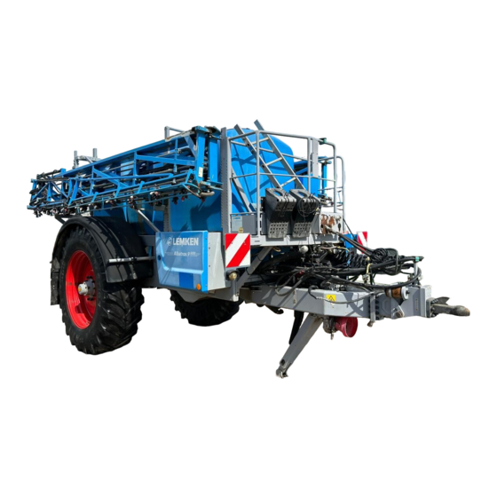
Design and function DESIGN AND FUNCTION Overview 1 Chassis with drawbar 6 Pump/pumps 2 Drawbar end section with 7 Control and connection centre drawbar eye 3 Axis 8 Induction hopper 4 Wheels 9 Lifting mast with swinging sys- 5 Main tank with integrated fresh 10 Boom water tank... -
Page 43: Chassis, General
Design and function Chassis, general The chassis forms the base for the attachment of other modules. The chassis consists of: Drawbar Drawbar extension End section Drawbar eye 6.2.1 Drawbar with end section and drawbar eye The drawbar is the connection between the chassis and the drawbar eye. The implement has a rigid or steerable drawbar. -
Page 44: Drawbar - Automatically Steerable (Trail Control)
The axle of the implement is implemented as a running axle or a braked axle. The permissible axle load is indicated on the Lemken axle type plate (1). The implement may only be used with a running axle if the empty weight of the tractor is at least double the permissible total weight of the filled implement. -
Page 45: Brake System
Design and function Brake system The implement may be equipped with: no brake system with a manually regulated air brake system with an automatic, load-dependent air brake system and pneumatic suspension with a hydraulic brake system 6.4.1 Without brake system For implements without brake systems, running axles (1) or brake axles without... -
Page 46: Manually Regulated Air Brake System
Design and function 6.4.2 Manually regulated air brake system Brake coupling (1) yellow (Control line) Brake coupling (2) red (Supply line) Air filter (3) Manual regulator(4) Double-release valve (5) - Page 47 Design and function Trailer brake valve (6) Compressed air tank (7) Drain valve (8) Combined brake cylinder (9)
- Page 48 Design and function Construction The air brake system consists of the following: Parking brake Operational brake Tear-off brake The individual brake functions are activated according to when the brake cylinder is actuated. Parking brake The spring accumulators of the brake cyl- inder can be activated or released with the red button of the double-release valve (1).
-
Page 49: Air Brake System With An Automatic, Load-Dependent Compressed Air Brake Valve And Pneumatic Suspension
Design and function Tear-off brake If the brake lines are disconnected when the device is removed from the tractor, the system automatically brakes with the operational pressure of the compressed air container. 6.4.3 Air brake system with an automatic, load-dependent compressed air brake valve and pneumatic suspension With the air brake system with automatic, load-dependent brake valve and pneu- matic suspension, the brake pressure is automatically adjusted by an automatic. -
Page 50: Hydraulic Braking System
Design and function The implement is equipped with a level controller in order to maintain the height of the implement. The actual height is detected by the link- age (3) and adjusted with the valve (4). The pneumatic suspension (1) is supplied with air via: ... -
Page 51: Fluid Circuit
Design and function Fluid circuit 6.6.1 Albatros 9/2000 Fresh water tank filling and emptying connections Induction hopper Fresh water tank Agitator nozzle Control valve Edge wetting Self-cleaning pressure filter Injector Flow meter Canister flushing nozzle Agitator Connection for cleaning gun... -
Page 52: Albatros 9/3000
Design and function 6.6.2 Albatros 9/3000 Fresh water tank filling and emptying connections Induction hopper Fresh water tank Agitator nozzle Control valve Edge wetting Self-cleaning pressure filter Injector Flow meter Canister flushing nozzle Agitator Connection for cleaning gun Internal cleaning, main tank... -
Page 53: Albatros 9/4000-5000-6000
Design and function 6.6.3 Albatros 9/4000-5000-6000 Fresh water tank filling and emptying connections Induction hopper Fresh water tank Agitator nozzle Control valve Edge wetting Self-cleaning pressure filter Injector Flow meter Canister flushing nozzle Agitator Connection for cleaning gun Internal cleaning, main tank... -
Page 54: Description
Design and function 6.6.4 Description The spray pump(s) (H) pump the spraying liquid via the selector valve (A) and suction filter (11) through the pressure limiting valve (19) to the distribution valve (C). In the 'Spray' setting of the selector valve (C) the spraying liquid is pumped via the control valve (3), the self-cleaning pressure filter (4) and the flow meter (5) to the segment valves (22) and the central bypass valve (23). - Page 55 Design and function The spraying liquid then flows to the membrane check valves and is sprayed from the nozzles. If spraying is interrupted with the master switch of the operating terminal, spraying is terminated by the closing of the segment valves (22) and the central bypass valve (23) is opened.
-
Page 56: Main Tank
Design and function Main tank The main tank is provided for the storage of water, spraying liquid and fertilizers. The vent valve/venting system (1) ensures that the main tank is vented during spray- ing and that pressure is released during filling. -
Page 57: Fresh Water Tank
Design and function By means of the drain valve (4) the content of the main tank can be drained in free fall into a suitable collection vessel or can be extracted by means of an external pump. Fresh water tank The fresh water tank is provided for the storage of fresh water. -
Page 58: Filter
Design and function 6.10 Filter Clean and functional filters are essential for fault-free work. The implement is equipped with a suction filter (1) or two suction filters (1) a pressure filter (2) The suction filter (1) filters the volume flow on the suction side of the pump. -
Page 59: Pump
Design and function 6.11 Pump The implement is equipped with either one or two pumps. The pump is intended for pumping spray- ing agents and liquid fertilizer. The pump is driven either mechanically or hydraulically. 1 Drive shaft 2 Gear unit 3 Suction area 4 Pressure area 5 Oil filling opening... -
Page 60: Hydraulic Drive
Design and function 6.11.2 Hydraulic drive In the case of hydraulic drive, the pump (1) is driven by a hydraulic motor (2). The speed of the pump is displayed on a separate display unit (3) or on the control terminal. -
Page 61: Control And Connection Centre
Design and function 6.12 Control and connection centre Selector valve Agitator pump valve Distribution valve Agitator control (Albatros 9/4000-5000-6000) Pressure filter (not illustrated) Flushing valve (not illustra- ted) Induction hopper valve Suction valve Suction filter 10 TankControl display 6.12.1 Selector valve... -
Page 62: Agitator Pump Valve
Design and function 6.12.2 Agitator pump valve The Albatros 9/4000,5000 and 6000 have an agitator pump valve for the agitator pump. Pictogram Function Description The main tank is filled by the agitator pump via a filler External hose to the suction connection. -
Page 63: Agitator Control
Design and function 6.12.4 Agitator control Pictogram Description According to the version of the implement, the maximum agita- tion effect of the agitator pump or the working pump is in the main tank. The agitation intensity can be continuously regulated. According to the version of the implement: ... -
Page 64: Induction Hopper
Design and function 6.12.7 Induction hopper Spraying agent can be fed into the main tank with the induction hopper. The in- duction hopper consists of the following components: Container (1) The container can be swivelled into the working or transport position. ... -
Page 65: Induction Hopper Valve
Design and function Edge wetting (9) Adhesion of spraying agent to the induction container is prevented with edge wet- ting. Cleaning gun (10) The cleaning gun can be used to clean larger spraying agent canisters. Suction valve(11) Suction from the induction container can be continuously regulated with the suc- tion valve. -
Page 66: Suction Valve
Design and function 6.12.9 Suction valve The suction valve is used to extract spraying agent from the induction hopper. Pictogram Function Description Induction Suction valve open Selection The suction strength can be continuously regu- lated. Closing Suction valve closed 6.12.10 Connections Hand washing container drain Hand washing container filler... -
Page 67: Pressure Limiting Valve
Design and function 6.12.11 Pressure limiting valve The pressure limiting valve (1) is used to adjust the maximum system pressure of the implement. The pressure limiting valve is set at the factory and must not be adjusted. 6.12.12 Hand washing container drain valve The hand washing container can be emptied with the drain valve (1). -
Page 68: Tank Control Filling Level Indicator
Design and function 6.12.14 TANK Control filling level indicator As an alternative to filling level indication with the scale (1), according to the control terminal used, the content of the main tank can be displayed on the control terminal. In addition, there is a separate indicator device on the control and adjustment cen- tre (2). -
Page 69: Filler Hose
Design and function 6.13 Filler hose Water or spraying liquid can be sucked in from external containers by means of a fil- ler hose (1). According to the equipment of the imple- ment, the filler hose can be wound onto the holder (5) for transportation. -
Page 70: Distance Detection
Design and function 6.15 Distance detection The distance pulses for automatic operation of the implement are detected from the wheel. In the case of braked axles, the speed is detected by means of a pole wheel which is integrated into the brake drum (1). In the case of running axles (2), the speed is detected by means of an external sensor (3). -
Page 71: Flow Meter
Design and function 6.16 Flow meter The flow meter (1) records the amount of spraying liquid which flows to the nozzles. The control terminal displays the litres per minute (l/min) which are sprayed. 6.17 Pressure measuring device The pressure measuring device is provided for monitoring the spray pressure (Auto- matic mode) and for the indirect indication of filter contamination. -
Page 72: Electro-Hydraulic Control
Design and function 6.19 Electro-hydraulic control 6.19.1 Standard The electro-hydraulic functions of the implement are controlled with a hydraulic control block (1). The electrical power supply is provided by the operating terminal. The following functions of the implement can by controlled by the operating terminal using the electro-hydraulic control. -
Page 73: Control Terminals
Individual functions of the implement are operated and controlled with a control terminal. The implement can be equipped with the following control terminals: Spraydos COMFORT Terminal LEMKEN CCI-200 Terminal SPRAY-Control S UNI-Control S See the separate operating instructions for the particular operating terminal. -
Page 74: Spraydos
Design and function 6.20.1 Spraydos Individual functions of the implement are operated and controlled with the Spray- dos control terminal. According to the version of the implement, some of the switches are not active. These are indicated with red caps. The active switches are indicated with black caps. - Page 75 Design and function Switch / Name Function Position Indicator light Valve type / control constant Model* Display illumina- Control terminal ON ted (On) ON / OFF Press 1 x Display not illu- Control terminal OFF minated (Off) Spray ON Main switch Spray OFF Bottom Segment ON...
- Page 76 Design and function Foam left Left Neutral position Middle Foam marking Foam right Right Spray asymmetrically Left left Limit nozzle Neutral position Middle (Edge nozzle) Spray asymmetrically Right right Fold out Boom 1 and 2 Middle symmetrical Fold Fold in Bottom Fold out Boom 3...
-
Page 77: Spray-Control S
Design and function 6.20.2 SPRAY-Control S The control unit of the implement with the operating terminal SPRAY-Control S comprises the switch box and the operating terminal. According to the version of the implement, some of the switches are not active. These are indicated with red caps. -
Page 78: Comfort- Terminal
The operating terminal enables trans- fer of data to an external PC using a USB stick. At present the Trac-Leader II program and Section-Control cannot be implemented with the LEMKEN CCI-200 terminal. See the separate operating instructions for the operating terminal. -
Page 79: Multifunction Handle
Multifunction handle The multifunction handle facilitates the operation of the implement with the COM- FORT terminal and LEMKEN CCI-200 terminal. A total of 24 functions can be con- trolled with the control keys and switches (x). The individual key panels can be selected with the switch (x). The switch (x) is de- signed so that it must be held in the top or bottom position for the control of the upper or lower key panel. -
Page 80: Spraying
Design and function 6.21.2 Spraying For this function the switch (x) must be in the middle position. Function Programmed quantity (l/ha (100%) is sprayed On or Off Segments boom switched in from right to left Segments boom switched in from left to right Segments boom switched off from left to right... -
Page 81: Boom
Design and function 6.21.3 Boom For this function the switch (x) must be held in the bottom position. Function Operation in Manual or Automatic mode (DISTANCE control) Raise boom Lower boom No function No function Raise left boom arm Raise right boom arm ... -
Page 82: S-Box
Design and function 6.22 S-Box The COMFORT terminal and the LEMKEN CCI-200 terminal can be equipped with an additional row of switches for the electrical segment valves. This makes control easier and enables nest treatment. Switch position 2 and 6... -
Page 83: Height Adjustment
Design and function 6.23 Height adjustment The height adjustment of the boom is car- ried out with a hydraulic cylinder on the lift- ing mast (1). Vertical movements are ab- sorbed by a damper. 6.24 Swing suspension and slope compensator The swing suspension (1) holds the boom horizontal. -
Page 84: Electrical Or Electro-Hydraulic - Non-Isobus Control Terminal
Design and function 6.24.2 Electrical or electro-hydraulic - non-ISOBUS control terminal The slope compensation of the boom can be directly controlled electrically or elec- tro-hydraulically with the potentiometer of the control terminal. The angle sensor (1) detects the angle be- tween the middle section and the swing suspension. -
Page 85: Distance Control
Design and function 6.26 DISTANCE Control A sensor (1) on the right and left side of the boom detects the distance of the boom from the target surface. The angle of the chassis is detected by a gyroscope on the chassis (2). The angle of the boom is detected by a gy- roscope on the boom (3). -
Page 86: Hydraulic Flow Dividers And Pressure Limiting Valves
Design and function Additional dampers (4) minimise swinging of the boom. The COMFORT terminal automatically controls the boom according to ground conditions. See the DISTANCE Control operating instructions. 6.27 Hydraulic flow dividers and pressure limiting valves A hydraulic flow divider (1) is provided for each of the functions symmetrical folding of the boom and separate folding of the ends. -
Page 87: Boom
Design and function 6.29 Boom 1 Boom 2 Height adjustment 3 Middle section 4 Arm 1 5 Arm 2 6 Arm 3 7 Collision pro- 8 Nozzle holder tector The boom (1) is designed for mounting the nozzle holders (8). 2 or 4 nozzle holders (8) are provided per metre of the working width of the boom. -
Page 88: Single Nozzle Holder
Design and function 6.31.1 Single nozzle holder One nozzle (1) can be fitted to each of the single nozzle holders (3). 6.31.2 Three-nozzle holder Up to three nozzles (3) can be fitted to each of the three-nozzle holders. The re- quired nozzle (1) is selected by rotating the nozzle holder. -
Page 89: Four-Nozzle Holder
Design and function 6.31.3 Four-nozzle holder Up to four nozzles (1) can be fitted to each of the four-nozzle holders (4). The required nozzle (1) is selected by rotating the noz- zle holder. There is a locking position between the in- dividual nozzles in order to close the noz- zle holder. - Page 90 Design and function Depending on the version, Vario Select nozzle holders can be equipped with 2 or 4 distributor valves (3). Via the segment valves (4), each distribu- tor valve (3) supplies the distribution (5) to the Vario Select nozzle holders (6).
-
Page 91: Nozzles
Design and function 6.32 Nozzles 6.32.1 General Various nozzles can be fitted to the nozzle holders. Each nozzle type has a differ- ent volume flow, spray pattern, drop size and nozzle characteristics. The liquid which is to be sprayed, the environmental conditions, the nozzle characteristics and official regulation such as distance conditions, drift reduction classes etc. -
Page 92: Drag Hose
Design and function 6.33 Drag hose The drag hoses (1) are intended for the application of liquid fertilizer. Burning of foliage is hardly possible, due to the direct application onto the ground. The drag hoses (1) may only be used with deflector hoops (2). -
Page 93: Boundary Nozzles
Design and function 6.35 Boundary nozzles Boundary nozzles are intended for sharp-edged spraying. Asymmetrical nozzles with the same size and comparable nozzle characteristics to those used in the boom are used as boundary nozzles. Boundary nozzles can be switched manually or electrically. 6.35.1 Manual With manually switched boundary nozzles, the last right and left nozzle holder on the boom is implemented as a three-nozzle holder. -
Page 94: Boom Lighting
Design and function 6.37 Boom lighting The boom lighting (1) is provided for illumi- nation of the boom when spraying in the dark. 6.38 Foam marking When spraying without tracks, the next track can be marked by foam marking. The flakes of foam which are deposited at regular intervals provide a clearly visi- ble marking line, which dissolves without residue after a time. -
Page 95: Preparations On The Tractor
Preparations on the tractor PREPARATIONS ON THE TRACTOR Overview The following preparations must be made before attaching the implement to the tractor: Check the pressure in the tyres of the tractor. Provide and check the necessary electronics connections. ... - Page 96 Preparations on the tractor The following sockets must be available on the tractor for the supply to the elec- tronic consumers of the implement: Consumer Volt Socket Lighting system DIN ISO 1724 Implement control terminal DIN 9680 Display for monitoring the speed DIN 9680 of the hydraulic pump drive Boom lighting / Relay box...
-
Page 97: Provide And Check The Necessary Hydraulic Connections
Preparations on the tractor 7.1.3 Provide and check the necessary hydraulic connections. DANGER The hydraulic brake system must only be connected to the con- nector on the tractor which is intended for the brake system. The connectors on the tractor must match the connectors on the implement. -
Page 98: Installation Of The Control Terminal
Preparations on the tractor 7.1.4 Installation of the control terminal Install the bracket for the control terminal within easy reach and within the field of view of the user. Take care that no electric cables or fluid lines are damaged when drilling the holes. -
Page 99: Determining The Driving Speed
Preparations on the tractor 7.1.5 Determining the driving speed. The driving speed must be known in order to accurately adjust the implement and for spraying. Usually, the driving speed of the tractor is displayed. However, the speed pulses for speed-dependent metering are obtained from the implement it- self. -
Page 100: Installing The Trail Control Operating Terminal And The Angle Sensor
Preparations on the tractor 7.1.6 Installing the TRAIL Control operating terminal and the angle sensor. Install the bracket (1) for the angle sen- sor (2) or the gyroscope (3) according to the separate TRAIL Control operating instructions. Attach the TRAIL Control operating ter- minal to the control terminal of the im- plement. -
Page 101: Mounting The Hydraulic Pump Drive Display And The Hydraulic Line
Preparations on the tractor Version with COMFORT Terminal and LEMKEN CCI Terminal With an appropriately equipped ISOBUS terminal, TRAIL Control is an integrated part of the program. Mount the multifunction handle within easy reach of the user. Attach the supplied stickers (1) for the key assignment of the multifunction han- dle in the field of view of the user. -
Page 102: Preparation Of The Device
Preparation of the device PREPARATION OF THE DEVICE CAUTION At the factory, the brakes of the new implement are only run-in to a limited extent. Because of this, the reduced braking effect of a new implement must be taken into account. Overview The following preparations must be made before attaching the implement to the tractor:... -
Page 103: Attaching The Implement
Preparation of the device Attaching the implement The implement may only be used in a horizontally aligned state and with a vertical angle of +/- 5° to the tractor. Slowly and carefully drive the tractor until the trailer coupling is about 20 cm from the drawbar eye of the implement. - Page 104 Adjustment can also be made with a different drawbar eye approved by LEMKEN. If a drawbar eye is replaced, the applicable road traffic regulations must be observed.
- Page 105 Preparation of the device WARNING Do not push the implement on the stand The stand is only intended for vertical loads. Pushing the imple- ment on the stand can cause damage to the stand. Switch off the tractor's engine. ...
- Page 106 Preparation of the device Mounting instructions: The maximum permissible length between the coupling point of the implement (x) and the attachment point on the tractor (x) is 230 mm up to a permissible total weight of ≤ 18.000 kg. ...
- Page 107 Preparation of the device Push the bolt (1) inwards. Push the locking bar (2) against the hook (3). The locking bar can also be set cross-wise. Fasten the safety chain (4) to an ade- quately dimensioned attachment point on the tractor.
- Page 108 Preparation of the device Implements with air brake systems Connect the implement brake couplings to the tractor. Place the manual control in the required position. Press the red button (6) to release the parking brake. Implements with hydraulic brake systems ...
- Page 109 Preparation of the device Remove the wedges (7). Place the wedges (7) in the holders (8) and secure them. Connect the electric cables and the hy- draulic lines.
-
Page 110: Calibrating The Trail Control Oil Quantity
Preparation of the device Calibrating the TRAIL Control oil quantity DANGER Ensure that there are no persons, animal or objects in the dan- ger area of the implement. The TRAIL Control oil quantity must be calibrated with the implement at a stand- still and in the transportation position. -
Page 111: Spraydos, Spray-Control S And Uni-Control S Operating Terminals
Preparation of the device 8.3.1 Spraydos, SPRAY-Control S and UNI-Control S operating terminals Switch off the implement operating terminal. Switch on the TRAIL Control control unit. Press the keys simultaneously and hold them pressed in order to calibrate the oil quantity. ... -
Page 112: Mounting And Testing The Drive Shaft
Preparation of the device Mounting and testing the drive shaft The end of the drive shaft which is marked with a tractor symbol must be mounted on the tractor. For drive shafts with a single wide angle joint, the wide angle joint must be mounted on the tractor. -
Page 113: Shortening The Drive Shaft
Preparation of the device 8.4.1 Shortening the drive shaft Pull the two halves of the drive shaft apart. Hold both halves of the drive shaft side- by-side at the shortest distance from the tractor. Mark the length which needs to be cut off on the outer protective tube. -
Page 114: Determining The Filling Capacity Of The Implement
Preparation of the device Add the operating instructions which are attached to the drive shaft on delivery to these operating instructions. Ensure that the drive shaft protector is secured against rotation by attaching the chains (1) to a fixed point. Determining the filling capacity of the implement To determine the permissible filling capacity of the implement [l/kg] the following data and procedures must be taken into account:... - Page 115 Preparation of the device Example table Data recorded e.g. Determina- e.g. Determina- e.g. from the type tion of the tion plate data data by cal- weighing culation Total permissi- Actual axle Permissible 3000 / 0.85 = weight load, imple- capacity of the 7500 3000 implement [kg]:...
- Page 116 Preparation of the device If fresh water fro cleaning is also carried (e.g. 400 l) this must be deducted from the filling quantity (e.g.: 3530 l – 400 l = 3130 l). For spraying liquids with a higher density, e.g. AHL solution with 30 weight % (=density factor 1.3 [kg/dm³]) the higher density must be taken into account by reducing the filling quantity (e.g.: 1 l AHL / 1,3 = ~ 0.77 l/kg AHL →...
-
Page 117: Installation Of The Correct Nozzles
Preparation of the device Installation of the correct nozzles The mesh size of the pressure filter and the nozzle filter must al- ways be the same as or smaller than the flow cross-section of the nozzles which are used. The details by the agricultural chemical manufacturer with regard to suitable mesh sizes must be observed. - Page 118 Preparation of the device Place the three-nozzle holder or the four-nozzle holder in the correct nozzles. If not all nozzles of a segment are required: in case of single nozzle holders, close the individual nozzles with caps (1). ...
-
Page 119: Measuring Litres
Preparation of the device A = Nozzle spacing 0.5 m H = Spraying height 1.0 m Measuring litres 8.7.1 General By measurement, it can be established whether the nozzles are worn, or what spray pressure on the pressure display corresponds to the actual spray pressure at the nozzle. -
Page 120: For Spraydos Operating Terminals
Preparation of the device 8.7.2 For Spraydos operating terminals Press the switch down in order to switch to Manual mode. Push up the spray switch. Press the switch to set the intended spraying pressure. Hold the measuring jug directly under the collecting hose or di- rectly under the nozzle for 60 seconds. -
Page 121: Calibrating The Speed Sensor
Preparation of the device Replace the nozzles. Repeat the measurement process. Have the nozzles checked on a test bench by an expert. Calibrating the speed sensor 8.8.1 General For automatic metering with the operating terminal, the distance pulses from the implement must be received and calibrated for 100 m. -
Page 122: For Spraydos Operating Terminals
Preparation of the device 8.8.2 For Spraydos operating terminals If the calibration value is known, make the following entries: Press the key to enter the value. Press one of the two keys to enter the value. Press the key to save the value. Carry out calibration as follows if the value is not known: ... -
Page 123: Calibrating The Flow Meter
Preparation of the device Calibrating the flow meter 8.9.1 General For automatic metering with the operating terminal, pulses from the implement flow meter must be received. In order for the pulses to be made available to the operating terminal: a known pulse value from the flow meter must be input to the operating terminal ... - Page 124 Preparation of the device Calibration with the container method With the container method, calibration is carried out by weighing the tractor and the implement before and after spraying and then entering the amount of water which has been sprayed into the operating terminal. The calibration is carried out as follows: ...
- Page 125 Preparation of the device Weigh tractor with empty implement (e.g.: approx 5400 kg). Calculate the weight of the water which has been sprayed. Example: 6000 kg – 5400 kg = 600 l sprayed water Press keys enter value.
- Page 126 Preparation of the device Calibration with the nozzle method With the nozzle method, the application quantity is measured for a single nozzle and then extrapolated for all the nozzles on the boom. As in this method the quantity for all the nozzles on the boom is extrapolated from a single nozzle, before calibration it must be ensured by measuring litres, that the intended nozzle corresponds to the average value for all the nozzles which are installed, see...
- Page 127 Preparation of the device Press the switch down to interrupt the spraying. Determine the exact content of the measuring jug. Multiply the value by the total number of installed nozzles. Example: Measuring jug content 2,0 l x 48 nozzles(24 m boom) = 96 l ...
-
Page 128: Mounting The Drag Hoses
Preparation of the device 8.10 Mounting the drag hoses DANGER To prevent damage to the implement or the drag hoses, the use of drag hoses is only permitted with deflector hoops. For good distribution of the liquid fertilizer, drag hoses require a spacing of 25 cm. The drag hoses can therefore only be mounted onto appropriately equipped booms. - Page 129 Preparation of the device Remove the blind plugs (1) on the sin- gle nozzle holders (2) for the drag ho- ses. Booms with single nozzle holders Remove the bayonet caps with the nozzles. Booms with multiple nozzle holders ...
- Page 130 Preparation of the device Carefully fold out the boom. The drag hoses (1) must not catch on any of the components or get caught in the wheels. Also take inclined positions of the im- plement and centrifugal forces in curves into account.
-
Page 131: Mounting The Drag Pipes
Preparation of the device 8.11 Mounting the drag pipes To prevent damage to the implement or the drag pipes, the use of drag hoses is only permitted with deflector hoops. The transportation width is increased by the drag pipes. WARNING ... - Page 132 Preparation of the device Booms with single nozzle holders Remove the bayonet caps with the noz- zles. Booms with multiple nozzle holders Rotate the nozzle holder to a free posi- tion. For booms with multiple nozzle holders (2), for which all positions of the nozzle holders are equipped with nozzles, re- move a bayonet cap with nozzle from...
-
Page 133: Operation
Operation OPERATION Draining the antifreeze WARNING Antifreeze may pollute the environment Antifreeze must not be drained into the sewers or onto sealed sur- faces. Drain the antifreeze into a container before operation. The implement is provided with antifreeze as frost protection ex-works. ... -
Page 134: Operation Below Freezing Point
Operation 9.2.2 Operation below freezing point The brake system of the implement may freeze if the imple- ment is operated at temperatures below freezing point. DANGER Only operate the implement under these conditions if: the compressed air reservoir has been drained. ... -
Page 135: Operation Terminal
Operation Operation terminal 9.4.1 General The master switch of the operating terminal enables the complete switch-off or switch-on of the boom by opening or closing the segment valves with simultane- ous closing and opening of the bypass valve. Individual segment valves are activated or deactivated with segment switches. The valves require a short lead time. -
Page 136: Spraydos
Operation 9.4.2 Spraydos The indicator lights of the segment switches and the master switch show the spraying function. In order for the operating terminal to automatically control the quantity applied per hectare (l/ha) the following settings must be made: Pulses/100 m ... -
Page 137: Filling And Emptying The Hand Washing Container
Operation Filling and emptying the hand washing container The content of the hand washing container is only for clean- ing purposes. WARNING If the content of the hand washing container is filled with cleaning or spraying agent, injury may be caused to the user or the envi- ronment. -
Page 138: Emptying The Hand Washing Container
Operation 9.5.2 Emptying the hand washing container To wash the hands or empty the hand wa- shing container: Open the valve (1). After washing the hands or emptying the hand washing container: Close the valve (1). -
Page 139: Filling And Emptying The Fresh Water Tank
Operation Filling and emptying the fresh water tank The content of the fresh water tank is only for cleaning pur- poses. If the fresh water tank is filled with cleaning or spraying agent, in- WARNING jury may be caused to the user or the environment. ... -
Page 140: Emptying The Fresh Water Tank
Operation Remove the cap (3). Attach the hose (4) to the filling connec- tor (5). Open the filler valve (6). Fill the fresh water tank. Monitor the level of the fresh water tank with the level indicator. To prevent the fresh water tank from over- flowing: ... -
Page 141: Filling The Main Tank With Water
Operation Filling the main tank with water Prevent the escape or back-flow of spraying agent Spraying agent must not escape into the environment from the main tank or flow back into the filler pipe when filling the main DANGER tank. Spraying agent which escapes or flows back can damage the en- vironment or affect the health of persons or animals by polluting drinking water. -
Page 142: Cap Of The Main Tank
Operation 9.7.1 Cap of the main tank If the implement is filled from the public water supply, care must be taken that the filling pipe must end at a distance of at least 10 cm above the maximum filling le- vel of the tank. -
Page 143: Filler Valve Connection
Operation 9.7.2 Filler valve connection Remove the cap (1). Attach the filler hose (2) to the filling connector. Switch the filler valve to 'Fill'. After this, the main tank can be filled. The filling speed can be continuously ad- justed with the filler valve. - Page 144 Operation Monitor the filling of the main tank with: the level indicator (1) the indicating devices on the operation and adjustment centre (2) the operating terminal To prevent the main tank from overflowing: Stop filling the main tank in good time. ...
-
Page 145: Selector Valve Connection
Operation Spraying agent can also be pumped into the main tank via the fill- ing connection using an external pump. Observe the relevant national and state regulations and stan- dards for the handling of spraying agents, in particular with re- gard to water protection zones, filling of implements etc. - Page 146 Operation Switch the selector valve to 'External'. Albatros 9/4000-5000-6000: Switch the agitator pump valve to 'Exter- nal'. Switch the distributor valve to spraying. The main tank will now be filled. Filling of the main tank must be stopped in good time to prevent it from overflowing.
- Page 147 Operation Switch the selector switch to the main tank. Albatros 9/4000-5000-6000: Switch the agitator pump valve to 'Agita- tion'. Spraying agent may also be sucked into the main tank via the suction connection. After filling with spraying agent, the content of the main tank must...
-
Page 148: Adjusting The Flushing Valve
Operation Adjusting the flushing valve Spraying agent in the water circuit can have a negative effect on the environment WARNING The flushing valve may only be adjusted: on an unsealed surface with fresh water from the fresh water tank It is advisable to make the adjustment on the area which is to be sprayed. - Page 149 Operation For Spraydos operating terminals Press the switch up in order to switch to Manual mode. Press the button up for 10 seconds in order to completely close the control valve. Press the button down for 3 seconds, in order to open the control valve a little.
-
Page 150: Filling The Main Tank With Spraying Agent
Operation Filling the main tank with spraying agent WARNING The main tank does not contain drinking water. Do not leave the implement unattended during filling. Observe the applicable national and state regulations. Calculate the required quantity of spraying agent exactly in or- der to avoid residual quantities. - Page 151 Operation The drain valve (1) must be closed and secured with the cap (2) before filling the main tank. If the drain valve (1) is not closed and se- cured: Pull the stirrup (3) to close the valve. Secure the drain valve with the cap (2).
-
Page 152: Cap Of The Main Tank
Operation 9.9.1 Cap of the main tank Spraying agent in the form of concentrate or ready mixed spraying agent can be filled directly into the main tank via the cover. Fold the lever (1) upwards. Push the ladder (2) upwards. ... -
Page 153: Filler Valve Connection
Operation 9.9.2 Filler valve connection Ready mixed spraying agent can be filled into the main tank via the filling valve connector. Place a suitable catching vessel under the filling valve connec- tion to ensure that spaying agent cannot run onto the ground in a uncontrolled manner. - Page 154 Operation Monitor the filling of the main tank with: the level indicator (1) the indicating devices on the operation and adjustment centre (2) the operating terminal To prevent the main tank from overflowing: Stop filling the main tank in good time. ...
-
Page 155: Selector Valve Connection
Operation 9.9.3 Selector valve connection Place a suitable catching vessel under the selector valve connec- tion to ensure that spaying agent cannot run onto the ground in a uncontrolled manner. Switch off the operating terminal. Switch on the pump. ... - Page 156 Operation Albatros 9/4000-5000-6000: Switch the agitator pump valve () to 'Ex- ternal'. Switch the distributor valve to spraying. The main tank will now be filled. Monitor the filling of the main tank with: the level indicator (1) ...
-
Page 157: Filling Via The Induction Hopper
Operation After filling with spraying agent, the content of the main tank must be agitated according to the spraying agent, see «, page 172». Adjust the power of the agitator control accordingly. 9.9.4 Filling via the induction hopper Fill the main tank with water or fertilizer according to the instructions of the rele- vant spraying agent manufacturer. -
Page 158: Shelf
Operation 9.9.5 Shelf The shelf can be folded up to accommo- date small spraying agent containers or a measuring jug. Fold the shelf (1) upwards. Swivel the holder (2) under the shelf (1). Swivel the shelf (1) onto the holder (2). The supplied measuring jug can be used for measuring and dosing the spraying agent. - Page 159 Operation Switch on the pump. Operate the pump at approximately 400 rpm. Switch the distributor valve to the induc- tion hopper. Regulate the power of the agitator con- trol as required. Fill approx. 10 l of the content from the main tank by opening the edge wetting lever in the induction hopper.
- Page 160 Operation The suction quantity, the edge wetting and the intensity of the agitator nozzle can be continually matched. The edge wetting must be adjusted so that the spraying agent which is to be flushed in, runs to the suction inlet over a lubricat- ing film.
- Page 161 Operation and cleaning of the induction system. After filling the spraying agent, cleaning the canisters and cleaning the induction hop- per system: Switch the distributor valve to spraying. After filling with spraying agent, the content of the main tank must be agitated according to the spraying agent, see «, page 172».
-
Page 162: Cleaning Empty Canisters
Operation 9.10 Cleaning empty canisters Spraying agent may cause damage to health and pollute the environment. CAUTION If the lever of the cleaning nozzle is not closed, you may by sprayed by the cleaning nozzle. You and the environment may become contaminated with residual particles of spraying agent. - Page 163 Operation If necessary, clean further empty canis- ters. Flush the induction hopper as required. Suck the induction hopper empty. Close the suction valve. Fold the cleaning nozzle (1) downwards. Close the cover Switch the selector switch to the main tank.
-
Page 164: Cleaning Gun On The Induction Hopper
Operation 9.11 Cleaning gun on the induction hopper Observe the relevant standards and regulations for cleaning the implement. The cleaning gun must only be operated with fresh water. Switch the selector switch to the fresh water tank. Switch on the pump. ... - Page 165 Operation Switch the distributor valve to the induc- tion hopper. Switch the cleaning gun lever up to ON. The effect of the cleaning gun can be con- tinuously regulated with the lever (1). Press the handle (2) to activate the cleaning gun (3).
-
Page 166: Flushing The Induction System
Operation Because of the limited content of the fresh water tank we recom- mend that for the cleaning of empty spraying agent canisters or flushing of the induction system with fresh water, fresh water is sucked in from a filler hose via the selector valve, See "Filling the main tank with water, page 139". - Page 167 Operation Agitator nozzle Open the suction valve so far that no liq- uid can escape from the induction con- tainer. After flushing, set the following levers down to the OFF position in order to clo- se the valves: ...
-
Page 168: Folding Out The Boom
Operation 9.13 Folding out the boom DANGER No persons or animals in the folding area Take care that there are no persons or animals in the folding area when folding out the boom. The height adjustment of the boom is equipped with a damper. Therefore, a spring travel of 10 cm must be taken into account. -
Page 169: With The Tractor Control Units
Operation 9.13.1 With the tractor control units Activate the appropriate tractor control unit to lift the boom up to the stops (1). Booms with symmetrical reduction Always activate the appropriate tractor control unit to fold the boom. For booms with symmetrical reduction, first fold out arms 1 and 2 and then arm ... -
Page 170: With Electro-Hydraulics And A Different Operating Terminal
Operation Press the switch up to fully fold out all the arms. Press the switch down to adjust the boom to the intended height. Booms with symmetrical reduction Press the button up to raise the boom to the stops. -
Page 171: Adjusting The Spring Stabiliser
Operation 9.14 Adjusting the spring stabiliser The spring stabiliser can be adjusted to suit the terrain. In the basic setting of the spring stabiliser, 15 chain links (1) are attached. Right hand stabilising chain Left hand stabilising chain Terrain Damping Stabilising chain Steep slope with firm Stronger... -
Page 172: Trial Operation Of The Implement
Operation 9.15 Trial operation of the implement Trial operation with water is necessary: for commissioning for familiarisation with the individual control functions before the first use with spraying agents after maintenance work after repairs Nozzles on the boom Only nozzles of the same type and size may be installed on the boom. - Page 173 Operation Switch the selector switch to the main tank. Switch the distributor valve to spraying. Switch the agitator control to maximum agitation. A trial spraying run should now be per- formed. Press the switch up to spray. All components should be checked for leaks and proper function during trial op- eration.
-
Page 174: Working With The Implement
Operation 9.16 Working with the implement Work may only be started after the implement has been correctly measured and calibrated and the spraying agent has been evenly mixed or dissolved. The following must be observed when wor- king: the manufacturer's instructions for the spraying agent ... - Page 175 Operation the swinging system the stabiliser Switch the selector switch to the main tank. Switch the distributor valve to spraying. Switch the agitator control to the intended agitation intensity. Switch on the pump. Operate the pump at a maximum of 550 rpm. ...
- Page 176 Operation Then the spraying runs in the inside of the area can be sprayed with application- orientated nozzles. Switch off the nozzles before turning around on the headland. If the implement drifts off track, for example on slopes: counter this by steering the tractor. ...
-
Page 177: Working On Uneven Ground Or Slopes
Operation 9.17 Working on uneven ground or slopes By adjusting the centre of gravity with the slope compensator, the boom can be adjusted to be parallel to the ground, even on uneven ground or on slopes. 9.17.1 Electrically with button (not ISOBUS operating terminal) The parallel position of the boom relative to the ground can be adjusted directly with the switch on the operating terminal in case of uneven ground or slopes. -
Page 178: Working Headlights
Operation 9.18 Working headlights The working headlights are switched on with a control terminal by means of a re- lay, or by plugging in a three-pin plug into a socket on the tractor. To switch off the working headlights, they must be switched off at the control terminal or the plug must be removed from the socket. -
Page 179: Foam Marking
Operation 9.19 Foam marking 9.19.1 General The foam should be mixed according to the intended duration time of the foam. Good foam formation can be achieved above 1% foam concentration. The concentration must be increased if the duration time of the foam marking is too low. -
Page 180: Commissioning
Operation 9.19.2 Commissioning Activate the compressor by plugging the connector into the tractor socket. Press the switch to the left until foam emerges from the left foam nozzle. Then press the switch to the right until foam emerges from the right foam noz- zle. -
Page 181: Boundary Nozzles
Operation 9.20 Boundary nozzles Boundary nozzles are intended for sharp-edged spraying at the edges of the field. Asymmetrical nozzles with the same size and comparable nozzle characteristics to those used in the boom are used as boundary nozzles. The appropriate boundary nozzles must always be used, if multiple nozzle holders are used with various nozzles on the boom. -
Page 182: Manually Switched Boundary Nozzles
Operation with application-orientated nozzles. Possible, the tracks can be set up when the crop is planted. 9.20.1 Manually switched boundary nozzles Boundary nozzles of the same size and with comparable nozzle characteristics analogous to the normal nozzles must be used. Check that the boundary nozzles are to be positioned in the last nozzle holder on the left and right of the boom or in the boundary nozzle holder on the basis of the ... -
Page 183: Electrically Switched Boundary Nozzles
Operation 9.20.2 Electrically switched boundary nozzles General Boundary nozzles of the same size and with comparable nozzle characteristics analogous to the normal nozzles must be used. Check that the boundary nozzles are to be positioned in the last nozzle holder on the left and right of the boom or in the boundary nozzle holder on the basis of the ... - Page 184 Operation 9.21 Edge nozzles Edge nozzles are used to extend the working width and can be activated manually or electrically. The angles of the edge nozzles are set at the factory and must not be adjusted. If the angle of the edge nozzles is changed: ...
-
Page 185: Manually Switched Edge Nozzles
Operation 9.21.1 Manually switched edge nozzles Determine the following values on the basis of the intended conditions of use and the nozzle table: Values to be programmed into the operat- Spraying width (m) ing terminal: Number of nozzles (pcs.) ... -
Page 186: Electrically Activated Edge Nozzles Switched With Spraydos
Operation 9.21.2 Electrically activated edge nozzles switched with Spraydos The electrically activated spraying nozzles are controlled with the first and last segment switch. Check whether the values for the spraying width (m) and the number of nozzles in the first and last segments (5 or 6 nozzles) are correctly programmed on the basis of the intended conditions of use and the nozzle table. -
Page 187: Folding In The Boom
Operation 9.22 Folding in the boom The boom can be folded in with the tractor control units, or with the electro-hydraulics and an operating terminal DANGER No persons or animals in the folding area Take care that there are no persons or animals in the folding area when folding out the boom. -
Page 188: With The Tractor Control Units
Operation 9.22.1 With the tractor control units Activate the appropriate tractor control unit to lift the boom up to the stops (1). Carefully fold in the boom (2). Lower the boom (2) into the transport locks and the front (3) and rear (4). Booms with symmetrical reduction ... -
Page 189: With Electro-Hydraulics And The Spraydos Operating Terminal
Operation 9.22.2 With electro-hydraulics and the Spraydos operating terminal Activate the appropriate electro-hydraulic control unit on the tractor. The boom (1) must be raised up to the stops (2) to fold in the boom. Press the switch up to raise the boom to the stops. - Page 190 Operation Press the switch down to lower the boom into the transport locks (2 and 4). Booms with symmetrical reduction Press the switch up to raise the boom to the stops. Press the switch down to fully fold in arm ...
-
Page 191: With Electro-Hydraulics And A Different Operating Terminal
Operation Press the switch down to lower the boom into the transport locks (2 and 4). If you no longer require the electro-hydraulic system: Deactivate the appropriate electro-hydraulic control unit on the tractor. 9.22.3 With electro-hydraulics and a different operating terminal See the separate operating instructions for the particular operating terminal. -
Page 192: System Cleaning With Partially Filled Main Tank Using The Spraydos Operating Terminal
Operation 9.23 System cleaning with partially filled main tank using the Spraydos operating terminal In case of longer interruptions to spraying, the contents of the main tank must be pumped out or drained into another external container. If the implement cannot be sprayed empty for short interruptions to spraying, the system must be cleaned with the main tank partially filled. - Page 193 Operation Press the button up for a maximum of 12 seconds in order to close the electrical control valve. Switch on the pump. Operate the pump at minimum speed (350 rpm). Spray about 50% of the content of the fresh water tank onto an unsprayed area.
- Page 194 Operation Switch the distributor valve to spraying. Switch the agitator control to maximum agitation. Observe the information in the instruc- tions for the use of the spraying agent. Press the switch down in order to switch the operating terminal to Automatic mode.
-
Page 195: Spraying With Drag Hoses And Drag Pipes
Operation 9.24 Spraying with drag hoses and drag pipes Drag hoses Fit the drag hoses. In order for the drag hoses to better penetrate into the crop instead of being pulled over it, the speed of travel should be kept as low as possible. The use of drag hoses is only permissible with deflector hoops. -
Page 196: Cleaning
Cleaning CLEANING 10.1 General Spraying agent must not be drained on the edge of paths or pas- WARNING sed into the sewage system. Collected spraying agent must be transferred to the prescribed waste disposal facility (enquire from the relevant official agency) or re-used (after consultation with the relevant manufacturer of the spraying agent). -
Page 197: Emptying The Main Tank
Cleaning 10.2 Emptying the main tank 10.2.1 General If the content of the main tank cannot be properly sprayed, the spraying agent is to be disposed of in the proper manner. To empty the main tank the spraying agent must be pumped into an external tank, ... -
Page 198: Pumping Residual Quantities From The Main Tank
Cleaning 10.2.2 Pumping residual quantities from the main tank Spraydos Press the switch down to deactivate the nozzles. Press the key to switch off the operating terminal. Release the lock (1). Place the lock in the holder (2). ... - Page 199 Cleaning Switch on the pump. Operate the pump at the specified speed. After pumping: Switch off the pump. Uncouple the pumping hose. Close the coupling with the cap. Switch the selector switch to internal cleaning.
-
Page 200: Draining Spraying Agent Out Of The Main Tank
Cleaning 10.2.3 Draining spraying agent out of the main tank Place a collecting container (1) under the drain connector. Close the drain valve (2). Remove the cap (3). If large quantities need to be drained from the main tank, an external pump with a suction hose with 2"... -
Page 201: Emptying The Fresh Water Tank
Cleaning 10.3 Emptying the fresh water tank The fresh water tank can be emptied by: draining pumping out spraying If there are traces of spraying or cleaning agent in the fresh water tank, the contents of the fresh water tank may only be sprayed on the last area to be sprayed. -
Page 202: Pumping Out
Cleaning 10.3.2 Pumping out Spraydos Press the switch down to deactivate the nozzles. Press the key to switch off the operating terminal. Release the lock (1). Place the lock in the holder (2). Remove the cap (3). ... - Page 203 Cleaning Close the flushing valve (5). Switch the selector switch to the fresh water tank. Switch the distributor valve to pump- ing/external cleaning. The contents of the fresh water container can now be pumped out. Switch on the pump. ...
-
Page 204: Spraying
Cleaning 10.3.3 Spraying Spraydos Fold out the boom. Switch the selector switch to the fresh water tank. Switch the distributor valve to spraying. Switch the agitator control to minimum agitation. Close the flushing valve (5). ... -
Page 205: Internal Cleaning
Cleaning 10.4 Internal cleaning 10.4.1 General Internal cleaning must only be carried out with fresh water. After spraying, the damp inner walls of the main tank must be flushed with fresh water. Then the flushing water must be agitated and sprayed onto the last area which was sprayed. -
Page 206: Other Operating Terminals
Cleaning Switch the distributor valve to internal spraying for 1 seconds. At the same time, switch the selector switch to the main tank. Switch the selector valve to the fresh water tank for 5 seconds. At the same time, switch the distributor valve to internal cleaning for 5 seconds. -
Page 207: External Cleaning
Cleaning 10.5 External cleaning The implement must be externally cleaned as necessary. External cleaning should ideally be carried out on the last area treated. Only fresh water may be used for external cleaning. The cleaning water should not seep into the groundwater or sewer systems. - Page 208 Cleaning before inspection of the implement. Switch off the operating terminal. For the Spraydos operating terminal, press the switch down to deactivate the nozzles. Release the lock (1). Place the lock in the holder (2). ...
- Page 209 Cleaning Switch on the pump. Operate the pump at minimum speed (350 rpm). Remove the spray gun (1) from the hol- der (2). Remove the required length of hose from the hose reel (3). Press the handle (4) to activate the spray gun (1).
- Page 210 Cleaning After external cleaning: Jerk the hose and then release it. The hose automatically winds onto the ho- se reel (3). Place the spray gun (1) in the holder (2). Switch the distributor valve to spraying. Remove the lock from the holder (2). ...
-
Page 211: Cleaning The Filter
Cleaning 10.6 Cleaning the filter DANGER There is danger of contact with agricultural chemicals when cleaning the filter. Wear suitable protective gear when carrying out cleaning. 10.6.1 General When the implement is filled, the filter may only be cleaned when the pump is switched off. -
Page 212: Suction Filter
Cleaning 10.6.2 Suction filter Before cleaning the suction filter, the filling connection must be closed with a cap. Remove the lock (1). Loosen the union nut (3). Remove the suction filter (2). Clean the individual components of the suction filter with water and a soft brush. -
Page 213: Pressure Filter
Cleaning 10.6.3 Pressure filter In order to remove particles of dirt from the system, we recom- mend that the flushing valve is closed before the last spraying run of the day. Remove and clean the pressure filter after the last spraying run of the day. -
Page 214: Detaching The Implement
Detaching the implement DETACHING THE IMPLEMENT Before the implement is detached all tanks must be empty the drawbar must be in the middle position. the boom must be in the transport position. Only park the implement on a surface which as far as possible complies with the following requirements: ... - Page 215 Detaching the implement Hydraulic braking system Activate the implement parking brake. Remove the wedges (1) from the holders (2). Use the wedges (1) to secure the im- plement against rolling away. Without brake system Push the bolt (1) of the safety chain in- wards.
- Page 216 Detaching the implement All implements Release the wing nuts (1). Remove the lever (2) from the holder (3). Insert the lever (2) into the hydraulic pump (4).
- Page 217 Detaching the implement Select lowering of the implement with the lever (5): Position Function Right Lower stand Lower the stand by actuating the lever Continue to actuate the lever until the coupling device of the tractor is no lon- ger under load.
- Page 218 Detaching the implement Uncouple the brake hoses from the tractor. Fasten the brake lines to the holders on the implement. Uncouple the drive shaft from the tractor. Fasten the drive shaft to the holder on the implement. ...
-
Page 219: Winter Storage
Winter storage WINTER STORAGE WARNING Only use bio-degradable antifreeze without alcohol. Do not use liquid fertilizer. Observe the instructions for use and the safety data sheet of the antifreeze which is used. Light (UV radiation) and the effects of weather accelerate the age- ing process of the implement materials. -
Page 220: Before The Start Of The Season
Winter storage to prepare the implement for winter storage the content of the fresh water tank must be fully drained. 12.1 Before the start of the season If the implement has been put into winter storage with antifreeze, the antifreeze must be drained into a collection vessel before the next spraying session. -
Page 221: Maintenance And Repairs
Maintenance and repairs MAINTENANCE AND REPAIRS 13.1 Special safety instructions 13.1.1 General Risk of injury when carrying out maintenance and repair work There is always the risk of injury when carrying out maintenance and repair work. WARNING Use suitable tools, suitable climbing aids, platforms and support elements. -
Page 222: Immobilise The Implement For Maintenance And Repairs
Maintenance and repairs 13.1.4 Immobilise the implement for maintenance and repairs Risk of accidents when tractor starts up Injuries may occur if the tractor starts moving during maintenance and repair work. Switch off the tractor engine before carrying out any work on the WARNING implement. -
Page 223: Working On The Electrics
Maintenance and repairs 13.1.6 Working on the electrics The device will be damaged if it is connected to the power CAUTION supply while work is being carried out on it If the device is still connected to the power supply of the tractor, the device will be damaged if work is carried out on the electrics. -
Page 224: Environmental Protection
Maintenance and repairs Perform all work on the device with a suitable and functional tool only. This applies in particular to the use of lifting gear. Risk of accident due to tool slipping off If applying a large force, e.g. when loosening bolts, the tool may WARNING slip off. - Page 225 Maintenance and repairs The grease nipples are protected from dirt with protective caps. Replace missing or damaged protective caps immediately. Service the implement according to the section "Maintenance intervals". In addition, at the end of the season: Grease all cotter pins. ...
-
Page 226: Maintenance Intervals
Maintenance and repairs 13.4 Maintenance intervals Interval Action Hose connections Pins, bolts etc. Piston rod, hydraulic cylinder Hand pump Slider tubes Drive shaft Joints Drawbar eye Stand Drawbar bearings Steering cylinder Cables Axle linkage adjuster Axle camshaft Ladder Gear unit Gear unit connector sleeve Pump connector sleeve Lifting mast... - Page 227 Maintenance and repairs Interval Action Cable roller Boom Boom chains Screw connectors Hydraulic hoses Electro-hydraulic oil pressure filter Pneumatic brake air filter Selector and distributor valve Induction hopper Pump Pump pressure reservoir Axle Brake system...
-
Page 228: Oils And Lubricants
Maintenance and repairs 13.5 Oils and lubricants Component Oil / Lubricant Quantity per service Hand pump Super Fluid 46 approx. 1.5 l Pump drive gear unit approx. 2.8 l Mobilgear 632 (factory filling) Grease nipples and open Depending on lubrication Multi-purpose grease lubrication points points... -
Page 229: Drive Shaft
Maintenance and repairs 13.7 Drive shaft Use lithium-lubricated grease, consistency class NL-G12. The drive shaft must be serviced on the tractor side and the implement side. Protective tube Safety chain Sliding tube not illustrated (inside the protective tube) Joints 13.7.1 Protective tube The protective tubes of the drive shaft must be checked for damage and wear. -
Page 230: Drawbar And Towing Equipment
Maintenance and repairs 13.8 Drawbar and towing equipment All of the following lubrication points and grease nipples must be greased with multi-purpose grease. 13.8.1 Drawbar eye Lubricate the contact surface of the drawbar eye (1) every 8 operating hours. ... -
Page 231: Stand
Maintenance and repairs 13.8.2 Stand Lubricate the grease nipple of the stand (1) every 8 operating hours. 13.8.3 Drawbar bearings Lubricate the grease nipple of the draw- bar (1) every 8 operating hours. 13.8.4 Steering cylinder Lubricate the grease nipples of both steering cylinders (1) every 8 operating hours. -
Page 232: Axle
Maintenance and repairs 13.9 Axle 13.9.1 Linkage plate Lubricate the grease nipples of the link- age plate (1) on the left and right side of the axle every 50 operating hours. 13.9.2 Camshaft Lubricate the grease nipples of the cam- shaft (1) on the left and right side of the axle every 50 operating hours. -
Page 233: Gear Unit
Maintenance and repairs 13.10 Gear unit 13.10.1 Oil change The gear oil of the pump drive must be changed according to the specified inter- vals. Place a suitable collection container un- der the screw (1). Remove the screw (2). ... -
Page 234: Connection Sleeve
Maintenance and repairs 13.10.2 Connection sleeve The connection sleeve must be lubricated every 50 operating hours. Turn the drive shaft (1), which is discon- nected from the tractor, manually so that the grease nipple can be greased through the protector (2). ... -
Page 235: Lifting Mast
Maintenance and repairs 13.11 Lifting mast 13.11.1 Lifting mast and floating bearing Lubricate the two sliding surfaces of the lifting mast (1) with a brush every 8 op- erating hours. Lubricate the grease nipple of the float- ing bearing (2) every 8 operating hours. 13.11.2 Slide and swing guide ... -
Page 236: Cable Roller
Maintenance and repairs 13.11.3 Cable roller Check that the cable roller runs freely every 50 operating hours. Replace damaged cable rollers. Lubricate the grease nipple of the cable roller (1) every 8 operating hours. 13.11.4 Cable Check the cable (1) for damage and kinks every 50 operating hours. -
Page 237: Boom
Maintenance and repairs 13.12 Boom 13.12.1 General The following lubrication points are located on the left and right sides of the boom. The photos of the lubrication points only show one side of the boom. The number of lubrication points relates to the total of the left and right sides of the boom. 13.12.2 Vibration damper ... -
Page 238: Folding Joint (1)
Maintenance and repairs 13.12.3 Folding joint (1) Lubricate the 4 grease nipples of the fol- ding joint (1) every 8 operating hours. 13.12.4 Folding joint (2) Lubricate the 4 grease nipples of the fol- ding joint 2 (1) every 8 operating hours. ... -
Page 239: Folding Cylinder
Maintenance and repairs 13.12.5 Folding cylinder Boom with 2 folding cylinders Lubricate each of the 2 grease nipples on the base of the piston (1) and on the piston rod (2) of the folding cylinder (1) every 8 operating hours. Boom with 4 folding cylinders ... -
Page 240: Chains
Maintenance and repairs 13.12.7 Chains Lubricate the 4 chains (1)with multi- purpose grease or chain spray every 8 operating hours . 13.12.8 Folding joint (3) Lubricate the 4 grease nipples of the fol- ding joint 3 (1) every 8 operating hours. 13.12.9 Hydraulic lines Hydraulic lines must be checked regularly for damage and leaks. -
Page 241: Oil Filter Of The Electro-Hydraulic Control Unit
Maintenance and repairs 13.13 Oil filter of the electro-hydraulic control unit Dirty oil causes increased wear and damage to the hydraulic sys- tem of the implement. The filter element of the oil filter must therefore be replaced as soon as the red dirt indicator (2) becomes visible. If the filter element of the oil filter is not replaced immediately, un- filtered oil is pumped into the electro-hydraulic control unit. - Page 242 Maintenance and repairs Turn the handle (3) to the left and open the door. Place a suitable collection container un- der the oil filter (1). Open the filter pot (4) of the oil filter (1). Remove the filter cartridge. ...
-
Page 243: Air Brake
Maintenance and repairs 13.14 Air brake 13.14.1 General The air filter (1) of the air brake must be cleaned regularly. Park the implement on a level surface. Activate the tractor parking brake. Switch off the tractor engine. ... -
Page 244: Cleaning
Maintenance and repairs 13.14.3 Cleaning DANGER Persons can be injured by the spring pressure of the air filter. Take care that there are no persons in the danger area. Due to the spring pressure of the air filter, the components of the air filter may fall onto the ground in an uncontrolled manner. - Page 245 Maintenance and repairs Switch on the tractor engine. When the tractor engine is running, the brake system will automatically be filled with air. Check the seal of the air filter by listening for escaping air and with leak detector spray ...
-
Page 246: Adjustment Centre
Maintenance and repairs 13.15 Adjustment centre 13.15.1 Selector and distributor valve The selector valve (1) and the distributor valve (2) must only be lubricated with silicone grease. Lubricate the grease nipple of the selec- tor valve (1) with about 5 strokes of a grease gun every 50 operating hours. -
Page 247: Tightening Torques
Maintenance and repairs 13.16 Tightening torques 13.16.1 General information Once loosened, secure self-locking nuts against self-loosening by exchanging the nuts with new self-locking nuts. using safety washers. using thread-locking compounds, such as Loctite. The following tightening torques refer to screw threaded fittings not specifically mentioned in these operating instructions. -
Page 248: Bolts And Nuts Made Of V2A
Maintenance and repairs 13.16.3 Bolts and nuts made of V2A Diameter [Nm] 1.37 11.0 M 10 M 12 M 14 M 16 M 18 M 20 M 22 M 24 M 27... -
Page 249: Wheel Nuts
Maintenance and repairs 13.16.4 Wheel nuts The tightening torque for the wheel nuts (1) with centring spring ring (2) is 550 Nm. Remove the protective caps (3). Check the torque of the wheel nuts (1) after the first 8 operating hours ... -
Page 250: Checking Connections To The Tractor
Maintenance and repairs 13.17 Checking connections to the tractor 13.17.1 Hydraulic connections Risk of accident due to spraying hydraulic fluid Fluid (hydraulic oil) escaping under high pressure can penetrate WARNING the skin and cause severe injuries. In case of injury, seek medical attention immediately. -
Page 251: Pump
Maintenance and repairs 13.18 Pump 13.18.1 General The pump on the implement may only be operated with an adequate oil level the correct pressure in the pressure reservoir correct diaphragms correctly functioning valves Have the following work carried out by a qualified, authorised person once a year: ... -
Page 252: Diaphragms
Maintenance and repairs 13.18.3 Diaphragms The pump diaphragms are damaged if the oil in the expansion vessel (1) has a white colour. Stop spraying immediately if the oil has a whit colour, as further operation of re- sults in damage to the pump. ... -
Page 253: Pressure In The Pressure Reservoir
Maintenance and repairs 13.18.4 Pressure in the pressure reservoir Check the pressure in the pressure reservoir: if the implement pressure measuring device shows large fluctuations. if there is heavy vibration in the pressure hoses of the implement. ... - Page 254 Maintenance and repairs Remove the protective cap (1). Check the pressure with a measuring device. Fill the pressure reservoir with a tyre in- flater valve to the specified pressure, if there is insufficient pressure in the pres- sure reservoir (2).
-
Page 255: Calibrating The Sensors
Maintenance and repairs 13.19 Calibrating the sensors The following must be calibrated annually: speed of travel indicator; see the operating instructions for the operating termi- nal and «Calibrating the speed sensor, page 119» flow meter; see the operating instructions for the operating terminal and «Calibrating the flow meter, page 121»... -
Page 256: Control Connections
Checking of the implement must only be performed by qualified, authorised per- sons, see «Test connections, page 300» 13.21.2 Pump output Connection for measuring pump output Albatros 9/2000 Albatros 9/2000 (working and agitation pump) Albatros 9/4000-5000-6000 (working pump) Albatros 9/4000-5000-6000 (agitation pump) 13.21.3... -
Page 257: Pressure Measuring Device
Maintenance and repairs 13.21.4 Pressure measuring device Connection for measuring the pres- sure measuring device. 13.22 Work to be performed by a qualified. authorised person 13.22.1 Axle Before the start of the season, have the following work carried out by a quali- fied, authorised person: ... -
Page 258: Inspection Of The Implement
Maintenance and repairs 13.22.3 Inspection of the implement Every 2 years, have the following work carried out by a qualified, authorised person: measurement of the pump output measurement and calibration of the flow meter measurement of the pressure sensor 13.23 Information in case of faults and malfunctions Fault Reason... -
Page 259: Technical Data
Technical data TECHNICAL DATA 14.1 Dimensions... - Page 260 Technical data Length (L) Width (W) Height (H) [mm] [mm] [mm] Boom Albatros 9/ base Mini- Maxi- Mini- Maxi- Minimum Maximum B 21 5400 5900 2600 2800 3250 3600 2000 - 3000 B 27 5500 6000 2600 2700 3250 3600...
-
Page 261: Weights
Technical data 14.2 Weights 14.2.1 Empty weight Empty weight Albatros 9/ Axle load [kg] Support load [kg] Total weight [kg] 2000 3089 3460 3000 3236 3660 4000 4375 4960 5000 4973 5680 6000 5047 5860 The actual weights may deviate from the table, depending on the version of the implement. -
Page 262: Load Data Depending On The Permissible Wheels
Black background: res is less than the axle load A: …. = permissible axle load [kg] G: …. Total permissible weight [kg] Without a brake system Albatros 9/ 2000 3000 Wheel Maximum support load [kg] Maximum permissible speed [km/h] A: 4860... - Page 263 Technical data Albatros 9/ 4000 5000 6000 Wheel Maximum support load [kg] 1190 1830 2000 Maximum permissible speed [km/h] A: 6660 270/95 R 54 157 A2 G: 7850 A: 7000 300/95 R 52 159 A2 G: 8190 A: 7000 300/95 R 46 148 A8...
- Page 264 G: 11160 G: 12000 For implements without a brake system the towing tractor must have sufficient braking capacity for the implement and the tractor. With a brake system Albatros 9/ 2000 3000 Maximum support load [kg] Wheel Maximum permissible speed [km/h]...
- Page 265 Technical data A: 6660 A: 6000 270/95 R 54 157 A2 G: 7850 G: 7190 A: 7000 A: 6300 300/95 R 52 159 A2 G: 8190 G: 7490 A: 7000 A: 6300 300/95 R 46 148 A8 G: 8190 G: 7490 A: 7000 A: 6300 320/90 R 46 159 A2...
-
Page 266: Drawbar With End Section And Drawbar Eye
Technical data 14.3 Drawbar with end section and drawbar eye The drawbar has an interface for the end sections: Drawbar extension for the top suspension Without springing for the top and bottom suspension With springing for the top and bottom suspension The following end towing eyes, towing rings and ball couplings are provided for the end sections: Towing eyes... -
Page 267: Axles
Technical data 14.4 Axles 14.4.1 General Observe the applicable national regulations. The maximum permissible speed may be 25 or 40 Km/h, depending on the load bearing capacity of the wheels. Maximum permissible speed Running axle: 25 Km/h The implement may only be used with a running axle if the empty weight of the towing tractor is at least double the permissible total weight of the filled implement. -
Page 268: Explanation Of The Terms Offset And Track Change
Examples: Albatros 9/3000 with braked axle and track width 1500 mm. As according to the table the track width is listed as 1500 mm, the maximum per- missible tyre width of 315 mm must be taken into account. Wider wheels may not be fitted. -
Page 269: Wheel Rims
Albatros 9/6000 with braked axle and track width 2210 mm. As the track width as delivered is listed as 2210 mm in the table, the maximum tyre width is 810 mm. -
Page 270: Track Width
Technical data 14.7 Track width 14.7.1 Albatros 9/2000 and 3000 Size Track [mm] Maximum Track [mm] Maximum ty- of axle [mm] with ET + 70 tyre width with ET - 83 re width [mm] [mm] 1640 1500 1806 1790 1650... -
Page 271: Albatros 9/4000, 5000 And 6000
Technical data 14.7.2 Albatros 9/4000, 5000 and 6000 Size Track [mm] Maximum Track [mm] Maximum ty- of axle [mm] with ET + 70 tyre width with ET - 83 re width [mm] [mm] 1790 1650 1956 1840 1700 2006 1940... -
Page 272: Albatros 9/2000 And 3000
14.8.1 Automatic drawbar control with TRAIL Control Voltage 12 V DC Connection 3-pin DIN 9680 Electrical power supply Fuse 25 A Albatros 9/2000 and 3000 1500 mm (1) Albatros 9/4000 1700 mm Minimum track width Albatros 9/5000 1800 mm Albatros 9/6000 1900 mm approx. -
Page 273: Tyres
Technical data 14.9 Tyres Size Width Tyre radius maximum permissi- of tyres (Rstat) [mm] ble pressure (1) [bar] [mm] 25 km/h and 40 km/h 230/95 R 48 147 A2 270/95 R 48 153 A2 270/95 R 54 157 A2 300/95 R 52 159 A2 300/95 R 46 148 A8 320/90 R 46 159 A2 340/85 R 48 162 A2... -
Page 274: Use Of Own Wheels Or Wheels Which Are Not Listed In The List Of Wheels
Technical data All tyres permitted for a particular version (e.g. Albatros 9/2000) can be inter- exchanged. However, the maximum possible tyre width, the maximum permissible speed and the adjustment or replacement of the mudguards must be taken into account. Spraying liquids other than water (e.g. AHL) may have a greater weight. -
Page 275: Drive Shaft
Technical data If pairs of wheels are used with a lower load bearing capacity than the maxi- mum permissible axle load, the filling quantity of the tanks must be adjusted so that the maximum load bearing capacity of the wheels is not exceeded. ... -
Page 276: Pumps
Technical data 14.12 Pumps 14.12.1 Allocation Albatros 9/ Working pump Agitation pump 2000 AR 250 3000 2 x AR 160 4000-5000-6000 AR 250 AR 250... -
Page 277: Data For Each Pump
Technical data 14.12.2 Data for each pump Model AR 160 AR 250 Type Piston diaphragm pump Number of pistons Line connection Hose connection Internal Ø, suction side [mm] Internal Ø, pressure side [mm] Operating pressure [bar] Nominal pressure [bar] Permissible vacuum pressure [bar] Maximum suction height [m] Maximum pumping height [m] with 0... -
Page 278: Spraying Fluid System
Technical data 14.13 Spraying fluid system Spraying pressure range of implement with water [bar]: 1.0 – 8.0 Permissible system pressure [bar] Application quantity depending on pump, nozzles and speed of travel [l/ha]: 200 – 600 Connections Drain: Hose connector Ø 13 mm Hand washing container: ... -
Page 279: Oil Hydraulic System
Technical data 14.14 Oil hydraulic system 14.14.1 Implement system Required pressure of the tractor hydraulics for the implement hydrau- lic cylinder [bar]: Maximum permissible pressure [bar] The hydraulic system of the implement is filled with HLP 46 hydraulic oil accord- ing to ISO VG 46;... -
Page 280: Electronic Pressure Display
Technical data 14.15 Electronic pressure display Type: Liquid crystal display Pressure detection: electronic pressure sensor in the pipe cross-section of the boom Accuracy class: 1.6% of displayed value Resolution [bar]: Display range [bar] 0 – 16 Display area [cm] 4 x 1.5 Damping: electronic 14.16 Filter... -
Page 281: Tank Volume
Technical data 14.17 Tank volume Albatros 9/ Main tank Fresh water tank Hand washing con- tainer [l]: Nominal Actual vo- [l]: volume [l] lume [l]: 2000 2000 2200 3000 2900 3050 4000 3800 4000 5000 4800 5050 6000 5900 6200 ... -
Page 282: Boom
Technical data 14.18 Boom Implement Albatros 9/2000-3000-4000-5000-6000 Version B 21 B 27 Total working width [m] Operating pressure [approx. bar] Distance nozzles from ground, depend- 2.0 or 2.5 ing on tyres [approx. Boom swing range [approx. °] Transport width 2.70 2.40... -
Page 283: Boom
Technical data 14.19 Boom Albatros 9/2000-3000-3500-4000-4000- Implement Albatros 9/4000-5000-6000 5000-6000 Version B 30 B 33 Total working width [m] Operating pressure [approx. bar] Distance nozzles from ground, depend- 2.0 or 2.5 ing on tyres [approx. Boom swing range [approx. °]... -
Page 284: Boom
Technical data 14.20 Boom Implement Albatros 9/4000-5000-6000 Albatros 9/5000-6000 Version B 36 Total working width Operating pressure [approx. bar] Distance of nozzles from ground, depend- 2.0 or 2.5 ing on tyres [approx. Boom swing range [approx. °] Transport width 2.85 [approx. -
Page 285: Appendix
Appendix APPENDIX 15.1 General information about nozzles Each nozzle type has a different volume flow, spray pattern, drop size and nozzle characteristics. The liquid to be sprayed, the environmental conditions, the nozzle characteristics and official regulations such as distance conditions, drift reduction classes etc. -
Page 286: Nozzle Field Of Application
Appendix 15.2 Nozzle field of application Spray height Optimum Pressure Optimum Spray above Designation Material (1) spray height Size (2) range spray pres- angle target area (cm) (bar) sure (bar) (cm) Standard flat jet nozzles LECHLER LU POM/Cer. 120º 40 - 60 .01 - .08 1,5 - 5 1,5 - 2,5... -
Page 287: Nozzle Tables
Appendix 15.3 Nozzle tables 15.3.1 Nozzle sizes 01 - 05 Nozzle spacing: l/ha Flow 400 500 l/min 0,35 0,40 0,45 0,50 0,55 0,60 0,65 0,70 0,75 0,80 10,2 0,85 10,8 0,90 11,4 0,95 12,0 1,00 12,6 10,1 1,05 13,2 10,6 1,10 10,1 5,7 13,8 11,0... -
Page 288: Nozzle Sizes 06 - 10
Appendix 15.3.2 Nozzle sizes 06 - 10 Nozzle spacing: l/ha Flow 500 l/min 45,6 36,5 30,4 26,1 22,8 20,3 18,2 15,2 13,0 11,4 3,80 46,8 37,4 31,2 26,7 23,4 20,8 18,7 15,6 13,4 11,7 3,90 48,0 38,4 32,0 27,4 24,0 21,3 19,2 16,0 13,7 12,0 4,00 49,2 39,4 32,8 28,1 24,6 21,9 19,7 16,4 14,1 12,3... -
Page 289: Edge Nozzles
Appendix 15.5 Edge nozzles The vertical spraying angle of the swivel joint is approx. 30°. The meshing angle of the nozzles is 15°. Nozzle OC 12, brass Spray Edge Comparative Total spraying from crop distance pressure value over 50 width of an edge nozzle spraying nozzle... -
Page 290: Dosage Table For Liquid Fertilizer
Appendix 15.6 Dosage table for liquid fertilizer 15.6.1 Dosage table for drag hoses with 25 cm hose spacing: Mete- l/min L AHL (*)/ha ring apertu- 10,0 11,0 12,0 14,0 16,0 18.0 Ø km/h km/h km/h km/h km/h km/h km/h km/h km/h km/h km/h... - Page 291 Appendix Mete- l/min L AHL (*)/ha ring apertu- 10,0 11,0 12,0 14,0 16,0 18,0 Ø km/h km/h km/h km/h km/h km/h km/h km/h km/h km/h km/h 14.5 0.95 0.84 1.34 1.18 1.2 / 48 1.65 1.45 1.67 1.38 1.22 1.95 1.72 1.5 / 59 2.39...
-
Page 292: Dosage Table For Liquid Fertilizer Nozzle Sj 7
Appendix 15.6.2 Dosage table for liquid fertilizer nozzle SJ 7 Nozzle Water l/ha water for 50 cm nozzle spacing Pressu- (Co- km/h lour) l/min/ [bar] per nozzle .015 (Dark green) (Yel- low) (Dark blue) (Red) (Brown) (Grey) (White) (Light blue) (Dark green) - Page 293 Appendix Notes: Spraying height above the crop approx. 75 to 100 cm. Spraying pressure range 1.5 to 4.0 bar Spray direction against the direction of travel. For precise dosage we recommend measurement for the first ap- plication as well as once per year.
-
Page 294: Dosage Table For Five-Hole Nozzle Fl
Appendix 15.6.3 Dosage table for five-hole nozzle FL Nozzle Permissible metering aperture 0.8/1.0/1.2 mm Ø POM (black) 1.2/1.5/1.8 mm Ø POM (grey) Required nozzle caps SW 10 Metering aperture diame- 15 mm Mete- l/min AHL l / ha ring- H²O km/h apertu- Ø... -
Page 295: Ahl (28/1.28 Kg/L) Dosage Table For Id-, Idn-, Idk-, Idkn- And Fl Nozzles
Appendix 15.6.4 AHL (28/1.28 kg/l) dosage table for ID-, IDN-, IDK-, IDKN- and FL noz- zles Nozzle l/min AHL l/ha (Colour) [bar] km/h .015 (dark green) (yellow) .025 (magen- (dark blue) (red) (brown) (grey) (white) (light blue) (light green) (black) (*) 1.0 bar only for IDKN .01 ID/IDK: 20-90 1/ha (5-18 km/h) - Page 296 Appendix Notes: Spraying pressure measured at the nozzle. Lateral nozzle spacing 50 cm. Spraying height above crop approx. 50 cm. Spraying pressure range: ID nozzles: 2 to 3.5 bar IDN nozzles: 2 to 4 bar IDK nozzles: 1.5 to 2.5 bar IDK nozzles (.04/.05/.06): >1.0 bar - 2.5 bar FD nozzles:...
-
Page 297: Dosage Table For Liquid Fertilizer Nozzle Fd
Appendix 15.6.5 Dosage table for liquid fertilizer nozzle FD Nozzle l/min AHL l/ha (Colour) [bar] km/h (Red) (Brown) (Grey) (White) (Blue) (Green) (Black) - Page 298 Appendix Notes: The table refers to a nozzle spacing of 50 cm and l/ha values on the basis of AHL solution (28/1.28 kg/l). For liquid fertilizers of different density a correction factor must be applied. Spray direction against the direction of travel. ...
-
Page 299: Dosage Table, Six-Hole Nozzle Esi
Appendix 15.6.6 Dosage table, six-hole nozzle ESI Nozzle AHL l/ha Nozzle AHL l/ha (Co- (Colour) km/h km/h [bar] [bar] lour) (Green (Red) (Yel- (Brown) low) (Blue) (Grey) - Page 300 Appendix Notes: The table refers to a nozzle spacing of 50 cm and l/ha values on the basis of AHL solution (30/1.30 kg/l). For liquid fertilizers of different density a correction factor must be applied. Spraying pressure measured at the nozzle. ...
-
Page 301: Assignment Plan Of The Electro-Hydraulic Operation Unit; Positioning Of The Hydraulic Valves
Appendix 15.7 Assignment plan of the electro-hydraulic operation unit; Positioning of the hydraulic valves Raising and lowering the boom Raise Lower Fold the entire boom or arm 1 Fold out Fold in Fold arm 2 Fold out Fold in Hydraulic slope compensation Lower on left Lower on right Automatic drawbar steering... -
Page 302: Test Connections
15.8.1 Pump testing To test the pump, the power in l/min is measured with a test device. Albatros 9/2000 Albatros 9/3000 (working and agitation pump) Albatros 9/4000-5000-6000 (working pump) Pump testing - separate For separate inspections of the pump, the test equipment is only connected to the pump. - Page 303 Appendix Testing the pump in the implement system To test the pump in the implement system, the test equipment is integrated into the system of the implement. The pressure setting of the pump can be performed by the implement. Further tests can be performed during the pump test. ...
- Page 304 Appendix Testing the working pump - separate Loosen the union nut (1) on the working pump (2). Close the union nut (1) with a 1 ¼“ clos- ing cap. Screw a 1 ¼“ union nut with a hose to the pressure outlet of the agitator pump (3).
-
Page 305: Testing The Flow Meter
Appendix 15.8.2 Testing the flow meter Loosen the union nut (1). Connect the inlet of the test equipment to the loosened union nut with a 1 ¼“ hose connector (1). Connect the return line of the test equipment to the flow meter (2) with a 1 ¼“... -
Page 306: Testing The Pressure Measuring Device
Appendix 15.8.3 Testing the pressure measuring device The following possibilities exist for testing the pressure measuring equipment: Pressure measurement during the flow meter test (system test) For this measurement, the test equipment must be equipped with an integrated pressure measuring device. ... - Page 307 Appendix After testing the pressure measuring equipment, restore the implement to its original condition. Check that all lines are sealed tight.
-
Page 308: Technical Residual Quantities
Appendix 15.9 Technical residual quantities Residual quantity [l] Slope Level Contour line Albatros 9/ 2000 2000 3000 2900 4000 3800 5000 4800 6000 5900... -
Page 309: Matrices
Appendix 15.10 Matrices Boom (3) B 21 B 27 B 30 B 33 B 36 B 39 2-01 2-02 2-03 2-04 2-05 2-06 2-07 2-08 2-09 2-10 2-11 2-12... - Page 310 Appendix Boom (3) B 21 B 27 B 30 B 33 B 36 B 39 3-01 3-02 3-03 3-04 3-05 3-06 3-07 3-08 3-09 3-10 3-11 3-12...
- Page 311 Appendix Boom (3) B 21 B 27 B 30 B 33 B 36 B 39 4-01 4-02 4-03 4-04 4-05 4-06 4-07 4-08 4-09 4-10 4-11 4-12 4-13 4-14 4-15 4-16 4-17 4-18 4-19 4-20 4-21 4-22...
- Page 312 Appendix Boom (3) B 21 B 27 B 30 B 33 B 36 B 39 5-01 5-02 5-03 5-04 5-05 5-06 5-07 5-08 5-09 5-10 5-11 5-12 5-13 5-14 5-15 5-16 5-17 5-18 5-19 5-20 5-21 5-22...
- Page 313 Appendix Boom (3) B 21 B 27 B 30 B 33 B 36 B 39 6-01 6-02 6-03 6-04 6-05 6-06 6-07 6-08 6-09 6-10 6-11 6-12 6-13 6-14 6-15 6-16 6-17 6-18 6-19 6-20 6-21 6-22...
- Page 314 The following terminals can also be used for control: SprayControl S UniControl S LEMKEN CCI-200 Terminal (ISOBUS) COMFORT-Terminal (ISOBUS) Further optional versions: symmetrical reduction of the boom active air support AirVac and AirJet ...
- Page 315 Appendix Nozzles TeeJet XR 80/110 .015-.08; .015 up to 2 bar Lechler IDN 120 .015-.06; .015 up to 2 bar TeeJet DG 80/110 .015 / .02 / .03 / .04 TeeJet 110.02-.05 TeeJet AI 100 .015-.05 Lechler LU 90/120 347-.015 bis 567-.08; 347-.015 up to 2 bar Lechler LU 90/120 347-.015 bis 567-.08;...
-
Page 316: Noise, Airborne Sound
Noise, Airborne Sound NOISE, AIRBORNE SOUND The noise level of the implement does not exceed 70 dB (A) during work. NOTES As the version of equipment is depending from the order, the equipment of your implement and its description concerned may deviate in some cases. To ensure a continuously updating of the technical features, we reserve the right to modify the design, equipment and technique. -
Page 317: Index
Index INDEX Adjusting the flushing valve................146 Adjusting the spring stabiliser ................169 Attaching the implement ..................101 Brakes ........................ 100 Calibrating the flow meter ................... 121 Calibrating the speed sensor ................119 Calibrating the TRAIL Control oil quantity............108 Centring of the steering drawbar in the middle setting ......... - Page 318 Index MAINTENANCE ....................219 Maintenance intervals..................224 Measuring litres ....................117 Mounting and testing the drive shaft..............110 Mounting the drag hoses ..................126 Mounting the drag pipes ..................129 Nozzle tables ...................... 285 Operation below freezing point ................132 REPAIRS......................
Need help?
Do you have a question about the Albatros 9 and is the answer not in the manual?
Questions and answers